Design method for frequency domain low frequency compensation scanning signal

A technology of compensation scanning and design method, which is applied in the field of oil field vibrator seismic exploration, and can solve the problems of popularization and application of unfavorable low-frequency scanning signals, troublesome implementation, etc.

Active Publication Date: 2015-12-23
CHINA PETROCHEMICAL CORP +3
View PDF5 Cites 5 Cited by
  • Summary
  • Abstract
  • Description
  • Claims
  • Application Information

AI Technical Summary

Problems solved by technology

They used equal-frequency scanning frequency, gradually increased the source output for excitation, recorded the measured output of low-frequency sample points each time, and determined the actual output maximum output of the low-frequency sample points of the source. According to the fitted maximum displacement curve of the hammer and the system flow curve Focus, determine the low-frequency output curve of the vibrator, and actually test the generated signal. If the vibration of the vibrator exceeds the weight displacement or flow limit, reduce the measured amplitude value of the over-limit frequency point by 2-6%, and then repeat the above steps until The best low-frequency scanning signal is obtained when the vibration result does not exceed the weight displacement limit or flow limit. However, this method uses continuous repetition, which is more troublesome to implement, which is not conducive to the popularization and application of low-frequency scanning signals.

Method used


Image

  • Design method for frequency domain low frequency compensation scanning signal
  • Design method for frequency domain low frequency compensation scanning signal
  • Design method for frequency domain low frequency compensation scanning signal

Examples


Embodiment Construction

[0054] In order to make the above and other objects, features and advantages of the present invention more comprehensible, preferred embodiments are listed below and described in detail in conjunction with the accompanying drawings.

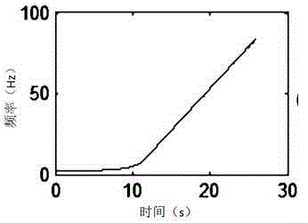
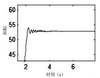
[0055] In order to satisfy the displacement of the vibrator weight in the low frequency band and the pump flow rate not exceeding the limit, the method of reducing the output is adopted, and the energy of the low frequency band is increased through time compensation to design the scanning signal. The essence of low-frequency scanning signal design is the design of low-frequency time-frequency curves, and then calculate the sinusoidal signal that can be used by the vibrator according to the nonlinear scanning signal formula.

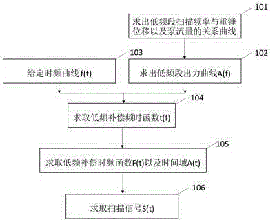
[0056] Such as figure 1 as shown, figure 1 It is a flow chart of the design method of the low-frequency compensation scanning signal in the frequency domain of the present invention.

[0057] In step 101, through the relat...


PUM


Abstract

The invention provides a design method for a frequency domain low frequency compensation scanning signal. The method comprises steps: a relation curve of a low frequency band scanning frequency and a hammer displacement and a pump flow is designed, the relation curve is transformed, and an optimal output of a low-frequency-band vibroseis is obtained; a routine time frequency curve f(t) is given; a new relation t (f) of scanning time and an instantaneous frequency is obtained; the time function t (f) is subjected to inverse transformation, a time frequency function F(t) is calculated, an optimal output A(f) of a frequency domain is converted to a time domain A (t) according to the t (f) curve; the time frequency function F(t) is subjected to integration, an instantaneous phase is calculated, and furthermore a sine vibroseis scanning signal is calculated. The scanning signal can expand low-frequency components of seismic data and low-frequency band data has strong energy, the excited seismic data has a high signal to noise ratio, and the seismic data quality of the vibroseis can be raised greatly.

Description

technical field [0001] The invention relates to the field of seismic exploration of an oilfield vibrator, in particular to a design method for low-frequency scanning signals of a nonlinear vibrator. Background technique [0002] Low-frequency seismic exploration technology is one of the main development directions of vibroseis application technology, and low-frequency scanning signal design is the key technology. In the early 1990s, when studying the characteristics of oil and gas accumulation in the North Caucasus and East Siberia, Russian scientists found that the amplitude of the power spectrum of the environmental noise above the oil area in the range of 1-10 Hz was significantly higher than that observed outside the oil area. As a result, the researchers analyzed that this may become an empirical indicator of oil and gas reservoirs. [0003] Low-frequency vibrator refers to a vibrator that can be used to excite signals with a minimum frequency lower than 5 Hz and has a...

Claims


Application Information

Patent Timeline
Patent Type & Authority Applications(China)
IPC IPC(8): G01V1/02
Inventor 于富文张剑胡立新赵国勇韩文功亓志伟刘梦花苏腾飞曹瑞山
Owner CHINA PETROCHEMICAL CORP
Why Eureka
Try Eureka