Manufacturing method of touch screen with IR induction zone

A manufacturing method and technology of the sensing area, which are applied in the input/output process of data processing, instruments, electrical digital data processing, etc., can solve the problems of easy wrinkles on the IR ink layer, high manufacturing cost of the touch screen, and insufficient printing accuracy. The effect of saving IR ink, reducing the production process, and reducing the production time

Active Publication Date: 2015-12-23
江门市威瑞电子科技有限公司
View PDF6 Cites 11 Cited by
  • Summary
  • Abstract
  • Description
  • Claims
  • Application Information

AI Technical Summary

Problems solved by technology

[0004] The above-mentioned touch screen replaces the traditional screen printing method by pasting the IR film on the IR hole. Although it can solve some disadvantages of the printing method, because the IR film is pasted through the optical adhesive layer, it is easy to use in the follow-up. Edge warping, falling off, etc. occur during the process, which affects subsequent production

Method used


Image

  • Manufacturing method of touch screen with IR induction zone
  • Manufacturing method of touch screen with IR induction zone
  • Manufacturing method of touch screen with IR induction zone

Examples


Embodiment 1

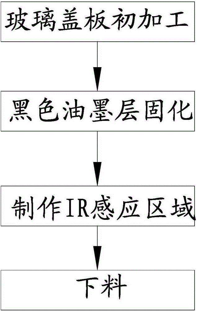
[0027] Such as figure 1 As shown, the manufacturing method of the touch screen with the IR sensing area has the following steps:

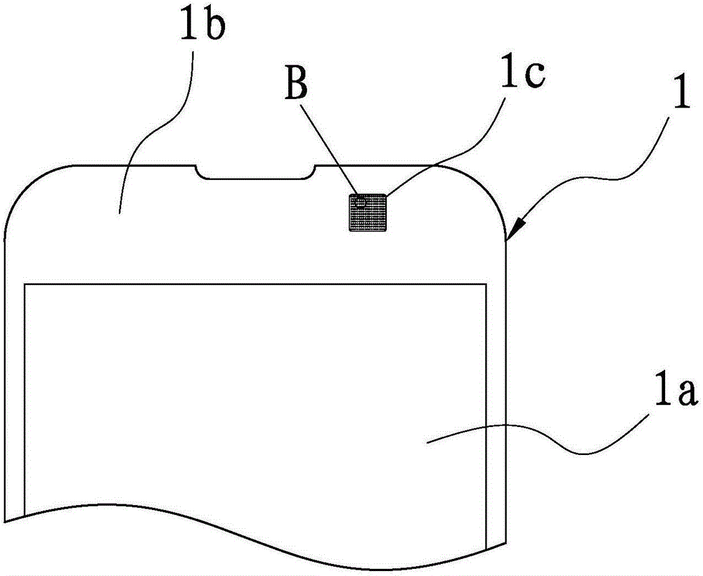
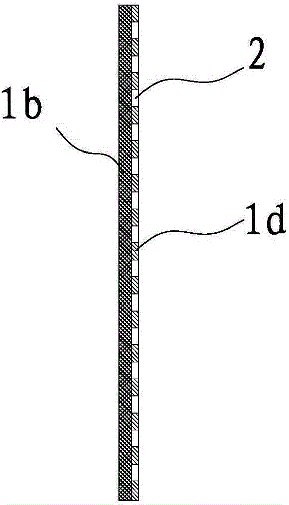
[0028] A. Initial processing of the glass cover: select the glass cover 1, which has a front and a back, and design a display area 1a and a non-display area 1b on the back of the glass cover 1. The display area 1a is mainly used for various applications on mobile phones In the information display window, the non-display area 1b is mainly used as a frame area, and a black ink layer 1d is attached to the non-display area 1b on the reverse side of the glass cover 1 . Normally, the black ink layer 1d is one layer. In this step, after the glass cover 1 is selected, the glass cover 1 needs to be cut into the size of a mobile phone, and the glass cover 1 needs to be cleaned and dried before cutting, so that the surface of the glass cover 1 can remove dust and other impurities to improve the quality of finished products. It should be noted that the blac...

Embodiment 2

[0037] In this embodiment, the manufacturing method of the touch screen with the IR sensing area is the same as that in Embodiment 1, the difference lies in the design of the IR sensing area 1c, specifically: the area of ​​the IR sensing area 1c is 30mm*100mm, laser engraving Specifically, it includes engraving a number of circular light-transmitting small holes 2 on the black ink layer 1d of the IR sensing area 1c, and the number of light-transmitting small holes 2 satisfy the following mathematical model: In the formula, a is the hole spacing in the horizontal direction, taking a value of 0.03mm; b is the hole spacing in the vertical direction, taking a value of 0.05mm; d is the hole diameter, taking a value of 0.03mm; T is the transmittance, taking The value is 17.1%, and its allowable error is ±0.1%.

Embodiment 3

[0039] In this embodiment, the manufacturing method of the touch screen with the IR sensing area is the same as that in Embodiment 1, the difference lies in the design of the IR sensing area 1c, specifically: the area of ​​the IR sensing area 1c is 50mm*60mm, laser engraving Specifically, it includes engraving a number of circular light-transmitting small holes 2 on the black ink layer 1d of the IR sensing area 1c, and the number of light-transmitting small holes 2 satisfy the following mathematical model: In the formula, a is the hole spacing in the horizontal direction, taking a value of 0.04mm; b is the hole spacing in the vertical direction, taking a value of 0.1mm; d is the hole diameter, taking a value of 0.05mm; T is the transmittance, taking The value is 16.8%, and its allowable error is ±0.1%.


PUM


Abstract

The invention provides a manufacturing method of a touch screen with an IR induction zone, and belongs to the technical field of touch screens. The problems that in the prior art, process steps are complex and the manufacturing cost is high are solved. The manufacturing method of the touch screen with the IR induction zone includes the steps of A, preliminarily machining a glass cover plate, wherein the glass cover plate is selected, a display zone and a non-display zone are designed on the back face of the glass cover plate, and a black ink layer is attached to the non-display zone; B, curing the black ink layer, wherein the glass cover plate manufactured in the step A is baked; C, manufacturing the IR induction zone, wherein the IR induction zone is designed in the non-display zone on the back face of the glass cover plate and subjected to laser etching treatment, namely, a plurality of small round light-transmitting holes are etched in the black ink layer in the IR induction zone, and a touch screen with the IR induction zone is preliminarily formed; D, performing discharging, wherein the manufactured touch screen is cleaned, and the finished product is discharged. According to the manufacturing method, only a few steps are needed, time is short, material consumption of the manufacturing process is small, and cost is low.

Description

technical field [0001] The invention belongs to the technical field of touch screens, and relates to a manufacturing method of a touch screen with an IR sensing area. Background technique [0002] At present, smart phones are all operated by touch screen, and in order to avoid misoperation when the face touches the screen of the phone during a call, general smart phones have IR (infrared ray) sensing function. The non-display area on the back of the glass cover of the mobile phone touch screen is covered with a covering ink layer, and an IR hole is arranged on the covering ink layer, and an IR ink layer is covered on the covering ink at a position corresponding to the IR hole. The IR ink layer can selectively transmit infrared light while shielding unwanted light, so that during a call, the IR ink senses the face and directly turns off the phone screen. The existing touch screen manufacturing process is cumbersome, and requires multiple printings and baking, which requires ...

Claims


Application Information

Patent Timeline
IPC IPC(8): G06F3/041
Inventor 王先玉夏永光
Owner 江门市威瑞电子科技有限公司
Why Eureka
Try Eureka