YIG electrically tunable filter magnetic circuit structure with high temperature stability

An ESC filter and stability technology, applied in circuits, waveguide-type devices, electrical components, etc., can solve the problems of large coil power consumption and large temperature drift of the filter, so as to reduce the magnetic circuit, reduce the temperature drift, The effect of improving temperature stability

Inactive Publication Date: 2015-12-23
THE 41ST INST OF CHINA ELECTRONICS TECH GRP
View PDF3 Cites 4 Cited by
  • Summary
  • Abstract
  • Description
  • Claims
  • Application Information

AI Technical Summary

Problems solved by technology

[0005] The purpose of the present invention is to solve the technical problem of large temperature drift of YIG electric tuning filter caused by large coil power consumption through reasonable magnetic circuit structure design and high-performance heat conduction bracket

Method used


Image

  • YIG electrically tunable filter magnetic circuit structure with high temperature stability
  • YIG electrically tunable filter magnetic circuit structure with high temperature stability
  • YIG electrically tunable filter magnetic circuit structure with high temperature stability

Examples


Embodiment 1

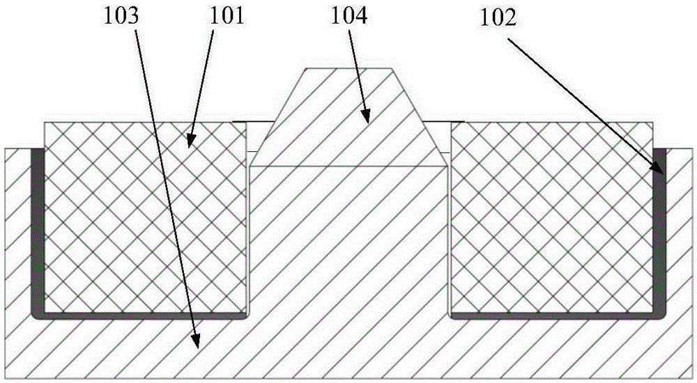
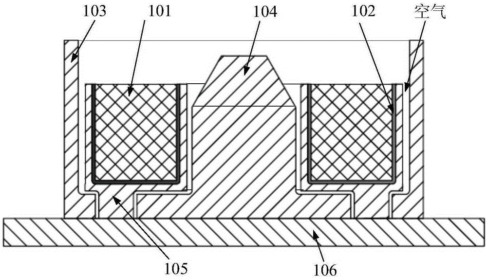
[0030] A high temperature stability YIG electric filter magnetic circuit structure, figure 2 is a schematic diagram of the magnetic circuit structure of the electronically tunable filter, image 3 is a schematic cross-sectional view of the magnetic circuit structure of the present invention, such as figure 2 with image 3 Shown:

[0031] The tuning coil 101 is fixed on the heat conduction bracket 105 through the heat conduction silica gel 102;

[0032] The upper part of the heat conduction bracket 105 is a U-shaped ring structure, which is placed in the annular groove formed by the casing 103 and the pole head 104; the upper part of the heat conduction bracket 105 is not in contact with the casing and the pole head;

[0033] The heat conduction support 105 is fixed on the cooling block 106 through the casing through a plurality of pillars provided at the bottom; the plurality of pillars are not in contact with the casing 103 .

[0034] Preferred:

[0035] The heat condu...

Embodiment 2

[0039] The present invention additionally provides a heat conduction bracket for YIG electric tuning filter, Figure 4 It is a perspective view schematic diagram of the heat conduction bracket of the present invention; Figure 5 is a schematic front view of the heat conduction bracket of the present invention; Image 6 It is a schematic diagram of the back side of the heat conduction bracket of the present invention; Figure 7 It is a schematic cross-sectional view of the heat conducting bracket of the present invention.

[0040] As shown in the figure, the upper part of the heat conduction bracket is a U-shaped ring structure, which is used to hold up the tuning coil; the lower part of the heat conduction support is a plurality of heat conduction pillars, which are used to fix the heat dissipation block; pole head contact.

[0041] When in use, the high-performance heat conduction bracket is fixed on the cooling block, and the cooling block is fixed on the casing, and the ...


PUM


Abstract

The invention relates to the technical field of microwave and millimeter wave tests, in particular to a YIG electrically tunable filter magnetic circuit structure with high temperature stability. The YIG electrically tunable filter magnetic circuit structure comprises a tuning coil, wherein the tuning coil is fixed on a heat conducting bracket through heat conducting silica gel; the upper part of the heat conducting bracket is of a U-shaped ring structure, and is arranged in an annular groove formed by a machine shell and a magnetic pole head; the upper part of the heat conducting bracket is not in contact with the machine shell and the magnetic pole head; the heat conducting bracket passes through the machine shell and is fixed on a radiating block through a plurality of supporting columns arranged at the bottom part; and the plurality of supporting columns are not in contact with the machine shell. Through the scheme, the tuning coil can be isolated from the machine shell completely, the temperature rise of the magnetic circuit can be reduced, the temperature drift of a YIG electrically tunable filter is reduced, and the temperature stability of the YIG electrically tunable filter is improved.

Description

technical field [0001] The invention relates to the technical field of microwave and millimeter wave testing, in particular to a magnetic circuit structure of a high temperature stability YIG electric tuning filter. Background technique [0002] YIG (Yttrium-Iron-Garnet) electronically tunable filter is a kind of microwave device developed by using the ferromagnetic resonance characteristics of yttrium iron garnet material. Because of its excellent spectral purity, ultra-wide operating bandwidth, and excellent linearity, it has become a key microwave component of broadband receiver instruments (such as broadband spectrum analyzers), and its performance directly determines the performance of broadband receivers. The direction of development of the instrument. However, in order to increase the frequency of the YIG electronically tuned filter, it is necessary to obtain a sufficiently large tuning magnetic field, so it is necessary to continuously increase the excitation power,...

Claims


Application Information

Patent Timeline
Patent Type & Authority Applications(China)
IPC IPC(8): H01P1/20
Inventor 高朋张志刚张枢刘金现朱伟峰霍建东
Owner THE 41ST INST OF CHINA ELECTRONICS TECH GRP
Why Eureka
Try Eureka