Photovoltaic generation box transformer substation

A photovoltaic power generation box and box-changing technology, which is applied in distribution substations, electrical components, substation/switch layout details, etc., can solve the problems of environmental pollution, maintenance time and high cost, and achieve convenient replacement of fuses, reduce maintenance costs, The effect of reducing the risk of environmental impact

Inactive Publication Date: 2015-12-23
NINGBO AUX HIGH TECH
View PDF3 Cites 2 Cited by
  • Summary
  • Abstract
  • Description
  • Claims
  • Application Information

AI Technical Summary

Problems solved by technology

[0003] Photovoltaic transformers are mainly used in photovoltaic power stations, and mainly undertake the task of boosting voltage. The reliability and safety of photovoltaic transformers directly affect the safe operation of photovoltaic power stations. Solar photovoltaic power generation occupies an important seat in the world's energy consumption in the 21st century. The grid-operated photovoltaic power generation box substation is to convert the alternating current from solar energy into the general station through the photovoltaic power generation box substation, and then use it for billing on the grid to realize solar power generation. The existing photovoltaic power generation box adopts the following structure - including low voltage room, high-voltage room, transformer and base, the radiator of the transformer is exposed outside, and an oil-immersed transformer is used. The high-voltage load switch is placed in the oil tank of the transformer. For oil-immersed transformers, there is a risk of polluting the environment after the transformer leaks oil. Replacing the entire transformer, high maintenance time and cost

Method used


Image

  • Photovoltaic generation box transformer substation
  • Photovoltaic generation box transformer substation
  • Photovoltaic generation box transformer substation

Examples


Embodiment Construction

[0016] The present invention will be further described below in conjunction with the accompanying drawings and specific embodiments.

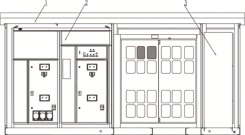
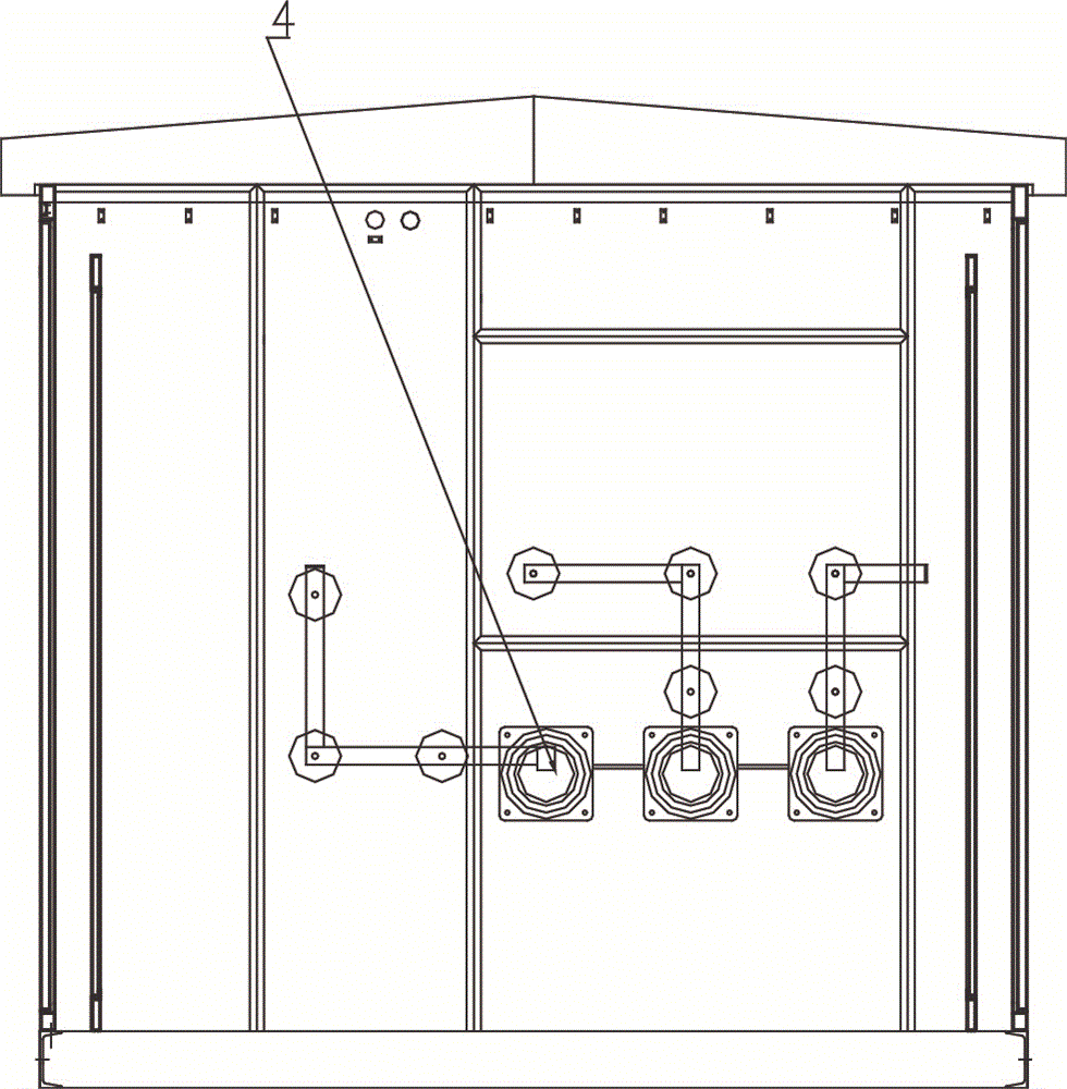
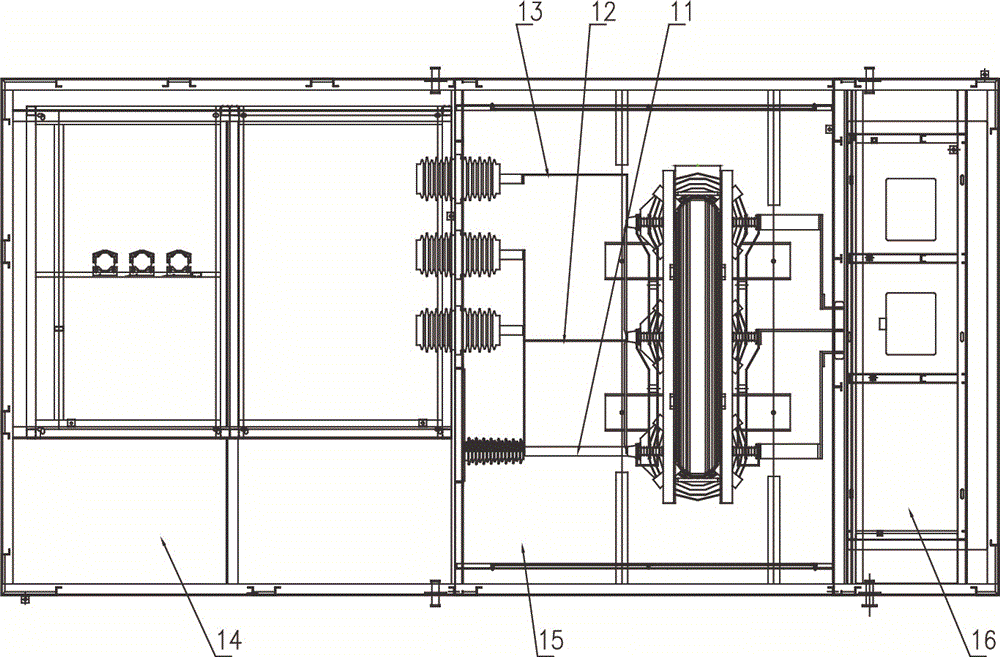
[0017] The photovoltaic power generation box change includes a box change casing 17, and the box change casing 17 is provided with a high-voltage chamber 14, a transformer chamber 15, and a low-voltage chamber 16, and a high-voltage cabinet 2 is placed in the high-voltage chamber 14. A transformer 7 is placed in the transformer chamber 15, a low-voltage cabinet 3 is placed in the low-voltage chamber 16, and the high-voltage side of the transformer 7 is connected with copper bars A11, copper bars B12, and copper bars C13. The copper bars The other side of A11, copper bar B12, and copper bar C13 is connected to the wall bushing 4, the wall bushing 4 is provided with a voltage equalizing ring, and the low voltage side of the transformer 7 is connected to the copper bar D6 and copper row E8, the copper row D6 and the other end of the copper row E8 ...


PUM


Abstract

A photovoltaic generation box transformer substation comprises a box transformer substation housing; a high voltage chamber, a transformer chamber and a low voltage chamber are arranged in the box transformer substation housing; a high voltage cabinet is arranged in the high voltage chamber; a transformer is arranged in the transformer chamber; a low voltage cabinet is arranged in the low voltage chamber; a high voltage side of the transformer is connected with a copper bar A, a copper bar B and a copper bar C; the other side of the copper bar A, the copper bar B and the copper bar C is connected with a wall bushing; a grading ring is arranged in the wall bushing; the low voltage side of the transformer is connected with a copper bar D and a copper bar E; the other end of the copper bar D and the copper bar E is connected with a breaker; the transformer is a dry type transformer, employs a duplex winding line, and a leading-out end is arranged above the transformer. The benefits are that the photovoltaic generation box transformer substation can reduce oil-immersed transformer oil leakage risks against environment, thus greatly improving product reliability, reducing maintenance cost, and the fuse can be conveniently replaced.

Description

technical field [0001] The invention relates to the technical field of photovoltaic transformers, in particular to photovoltaic power generation box transformers. Background technique [0002] Box-type transformer (also known as box-type substation) is a kind of high-voltage switchgear, distribution transformer and low-voltage power distribution device. It is a factory prefabricated indoor and outdoor compact power distribution equipment arranged according to a certain wiring scheme. , Transformer step-down, low-voltage power distribution and other functions are organically combined, installed in a moisture-proof, rust-proof, dust-proof, rodent-proof, fire-proof, anti-theft, heat-insulated, fully enclosed, movable steel structure box, mechanical and electrical integration It is a fully enclosed power transmission and transformation equipment. This kind of power transmission and transformation equipment is designed with traditional transformers in a box-type housing. It has s...

Claims


Application Information

Patent Timeline
Patent Type & Authority Applications(China)
IPC IPC(8): H02B7/06H02B1/48
CPCH02B7/06H02B1/48
Inventor 郑坚江
Owner NINGBO AUX HIGH TECH
Why Eureka
Try Eureka