Charging circuit and mobile terminal
A charging circuit and mobile terminal technology, applied in the field of electronics, can solve the problems of reducing battery cycle life, not suitable for mobile terminals, etc., and achieve the effects of ensuring battery cycle life, ensuring charging efficiency, and improving practicability
- Summary
- Abstract
- Description
- Claims
- Application Information
AI Technical Summary
Problems solved by technology
Method used
Image

Examples
no. 1 example
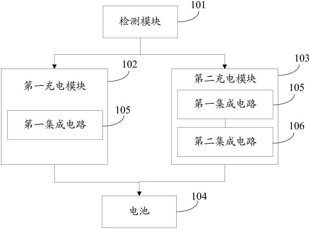
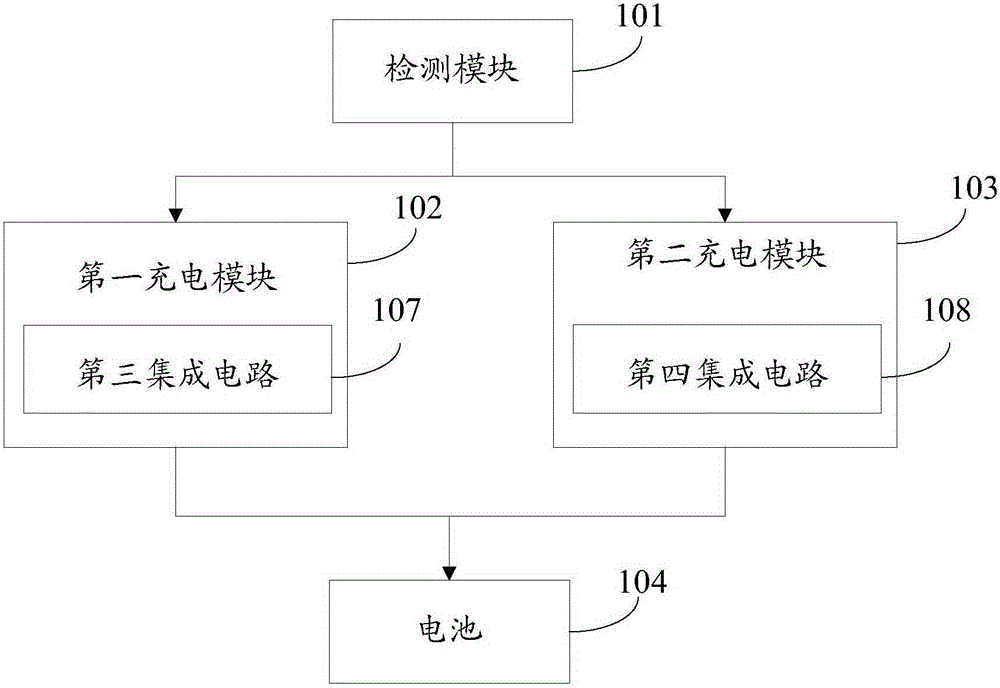
[0027] See Figure 1-2 , which shows a structural diagram of the charging circuit provided by the first embodiment of the present invention, the charging circuit may include:
[0028] The detection module 101 is used to detect the temperature of the battery.
[0029] Here, the detection module 101 detects the temperature of the battery, which provides data support for the subsequent conversion of the charging mode according to the temperature of the battery.
[0030] The first charging module 102 is configured to charge the battery 104 with a first current when the temperature of the battery is greater than or equal to a preset value.
[0031] Here, when the temperature of the battery is greater than or equal to a preset value, the first charging module 102 uses the first current to charge the battery 104 to ensure the charging efficiency of the battery 104, wherein the preset value is required by normal charging Threshold value of battery temperature.
[0032] The second c...
no. 2 example
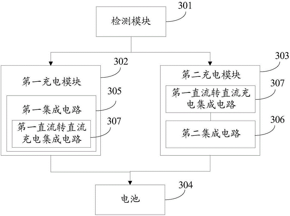
[0043] See image 3 , which shows a structural diagram of the charging circuit provided by the second embodiment of the present invention, the charging circuit may include:
[0044] The detection module 301 is used to detect the temperature of the battery.
[0045] Here, the detection module 301 detects the temperature of the battery, which provides data support for the subsequent conversion of the charging mode according to the temperature of the battery.
[0046] The first charging module 302 is configured to charge the battery 304 with a first current when the temperature of the battery is greater than or equal to a preset value. Specifically, the first charging module 302 includes a first integrated circuit 305 connected between the detection module 301 and the battery 304 . Preferably, the first integrated circuit 305 includes a first DC-to-DC charging integrated circuit 307 .
[0047] Here, since the first DC-DC charging integrated circuit 307 adopts the switch chargi...
no. 3 example
[0076] See Image 6 , which shows the structural diagram of the charging circuit provided by the third embodiment of the present invention, the charging circuit may include:
[0077] The detection module 601 is used to detect the temperature of the battery.
[0078] Here, the detection module 601 detects the temperature of the battery, which provides data support for the subsequent conversion of the charging mode according to the temperature of the battery.
[0079] The first charging module 602 is configured to charge the battery 604 with a first current when the temperature of the battery is greater than or equal to a preset value. Specifically, the first charging module 602 includes a third integrated circuit 605 connected between the detection module 601 and the battery 604 . Preferably, the third integrated circuit 605 includes a second DC-to-DC charging integrated circuit 607 .
[0080] Here, when the temperature of the battery is greater than or equal to a preset val...
PUM
 Abstract
Description
Claims
Application Information
 - R&D
- Intellectual Property
- Life Sciences
- Materials
- Tech Scout
- Unparalleled Data Quality
- Higher Quality Content
- 60% Fewer Hallucinations
Browse by: Latest US Patents, China's latest patents, Technical Efficacy Thesaurus, Application Domain, Technology Topic, Popular Technical Reports.
© 2025 PatSnap. All rights reserved.Legal|Privacy policy|Modern Slavery Act Transparency Statement|Sitemap|About US| Contact US: help@patsnap.com