Pneumatic type vertical lift remote monitoring system for crop image

A technology of remote monitoring system and remote control system, applied in the direction of closed-circuit television system, supporting machine, mechanical equipment, etc., can solve the problem of not being able to fully and comprehensively obtain live information of crops, affecting the value of agricultural guidance of crop monitoring system, and unable to meet the needs of fine observation To achieve the effect of facilitating crop growth, facilitating remote diagnosis, and diversifying monitoring effects

Inactive Publication Date: 2015-12-23
北京恺琳科技发展有限公司
View PDF3 Cites 20 Cited by
  • Summary
  • Abstract
  • Description
  • Claims
  • Application Information

AI Technical Summary

Problems solved by technology

[0002] At present, the traditional crop imaging system is mostly installed at a fixed height, and its fixed bracket is not convenient for transportation, and the installation process is complicated
In addition, with the continuous growth and development of crops, in order to achieve fine observation of different stages of crops, the monitoring equipment must be able to fine-tune within a certain range, and the existing crop imaging system cannot realize the observation distance, height, angle, etc. Adjustment
Therefore, as a crop imaging system, this design cannot meet the needs of fine observation of crops within a certain range in a complex field environment
What’s more, it is impossible to accurately and real-time monitor and warn of disasters such as crop freezing damage, drought, disease spots, insect damage, and stress, which seriously affects the actual agricultural guidance value of the crop monitoring system.
[0003] The existing crop monitoring systems all adopt fixed-point and fixed-height installation, and can only use the fixed-height installation point as the center of the circle to shoot from different angles, and the shooting effect is relatively simple
It is not yet possible to fully and comprehensively obtain live crop information, and it is impossible to effectively judge crop growth through the color, texture, shape and other characteristics of crop canopy, leaves, stems, etc. reflected in crop close-up images. decision service

Method used


Image

  • Pneumatic type vertical lift remote monitoring system for crop image
  • Pneumatic type vertical lift remote monitoring system for crop image

Examples


Embodiment Construction

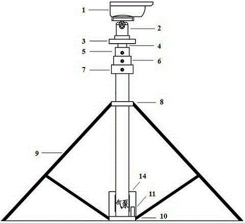
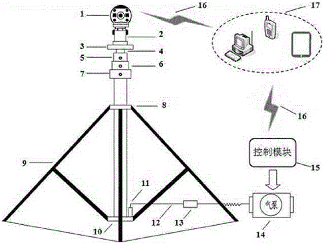
[0012] The present invention will be described in detail below in conjunction with the accompanying drawings and embodiments. Such as figure 1 with figure 2 As shown, the present invention includes: a 360-degree panoramic self-zooming network camera 1, a cloud platform 2, a camera support platform 3, a fourth floor lifting rod 4, a third floor lifting rod 5, a second floor lifting rod 6, a first floor lifting rod Rod 7, fixed sleeve rod 8, support frame 9, base 10, air nozzle 11, ventilation pipe 12, exhaust solenoid valve 13, air pump 14, remote control module 15, wired and wireless network 16, PC / mobile phone / tablet computer Wait for client 17.

[0013] After the present invention is installed, the Internet of Things remote control system of the remote server can be connected to the remote server through the wireless or wired network 16 through the wireless communication module, and the remote server can remotely control the air pump 14 and the exhaust gas through the cor...


PUM


Abstract

The invention discloses a pneumatic type vertical lift remote monitoring system for a crop image. The remote monitoring system comprises three parts including a pneumatic type lifting rod, a cradle head camera and an Internet of Things remote control system. The Internet of Things remote control system comprises a lifting rod state remote control module and a crop imaging remote control module. The lifting rod is arranged in a proper position in the field, the cradle head camera is fixed at a camera saddle at the top end of the lifting rod, and height adjustment of the lifting rod and camera imaging are both completed by the remote control system. The remote monitoring system has the advantages that the structure is simple, the height of the lifting rod and the shooting angle of the camera can be remotely and automatically adjusted, the crop shooting can be carried out from different lateral surfaces and orientations, the crop imaging from different lateral surfaces can be obtained, and the remote monitoring system is convenient for a user to master the crop growth situation more accurately and for a crop specialist to carry out remote diagnosis. Through the Internet of Things remote control system, the remote monitoring system supports snapshot and uploading of a field image and can utilize information, such as crop growth, color and texture, from the image.

Description

technical field [0001] The invention relates to a pneumatic vertical lifting crop image remote monitoring system, which belongs to the technical field of automatic control. Background technique [0002] At present, most of the traditional crop imaging systems are installed at a fixed height, and the fixed bracket is not convenient for transportation, and the installation process is complicated. In addition, with the continuous growth and development of crops, in order to achieve fine observation of different stages of crops, the monitoring equipment must be able to fine-tune within a certain range, and the existing crop imaging system cannot realize the observation distance, height, angle, etc. Adjustment. Therefore, as a crop imaging system, this design cannot meet the needs of fine observation of crops within a certain range in a complex field environment. It is even more impossible to accurately and real-time monitor and warn of disasters such as crop freeze damage, dro...

Claims


Application Information

Patent Timeline
Patent Type & Authority Applications(China)
IPC IPC(8): H04N7/18F16M11/24
Inventor 不公告发明人
Owner 北京恺琳科技发展有限公司
Why Eureka
Try Eureka