Peeling-off mechanism of corn harvesting machine

A corn harvester and cleaning mechanism technology, which is applied to harvesters, agricultural machinery and tools, and threshing equipment, can solve the problems of small grasping force, large longitudinal movement resistance, and easy slipping of corn ears, so as to reduce slipping and increase High gripping force, favorable peeling effect

Pending Publication Date: 2015-12-30
CHONGQING SHUANGEN AGRI MACHINERY MFG
View PDF0 Cites 2 Cited by
  • Summary
  • Abstract
  • Description
  • Claims
  • Application Information

AI Technical Summary

Problems solved by technology

[0003] The present invention intends to provide a peeling mechanism of a corn harvester to solve the problem of the small gripping force of a single steel roller in the prior art...

Method used


Image

  • Peeling-off mechanism of corn harvesting machine
  • Peeling-off mechanism of corn harvesting machine
  • Peeling-off mechanism of corn harvesting machine

Examples


Embodiment 1

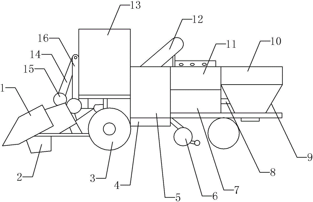
[0016] Instructions attached figure 1 The reference signs in include: cutting platform 1, cutting device 2, traveling wheel 3, traveling chassis 4, power mechanism 5, field returning machine 6, cleaning device 7, conveying path 8, hopper 9, beard ear separation device 10, Peeling device 11, lifting device 12, cab 13, second support arm 14, climbing wheel 15, first support arm 16.

[0017] as attached figure 1 In the peeling mechanism of the corn harvester shown, the power mechanism is arranged on the upper part of the walking chassis and is located in the middle of the whole machine, and the driver's cab is arranged on the walking chassis and is located in front of the power mechanism. The traveling wheels include front traveling wheels and rear traveling wheels, and the front traveling wheels and the rear traveling wheels are respectively located on both sides of the traveling chassis. The front of the walking chassis is equipped with a header device and a cutting device lo...

Embodiment 2

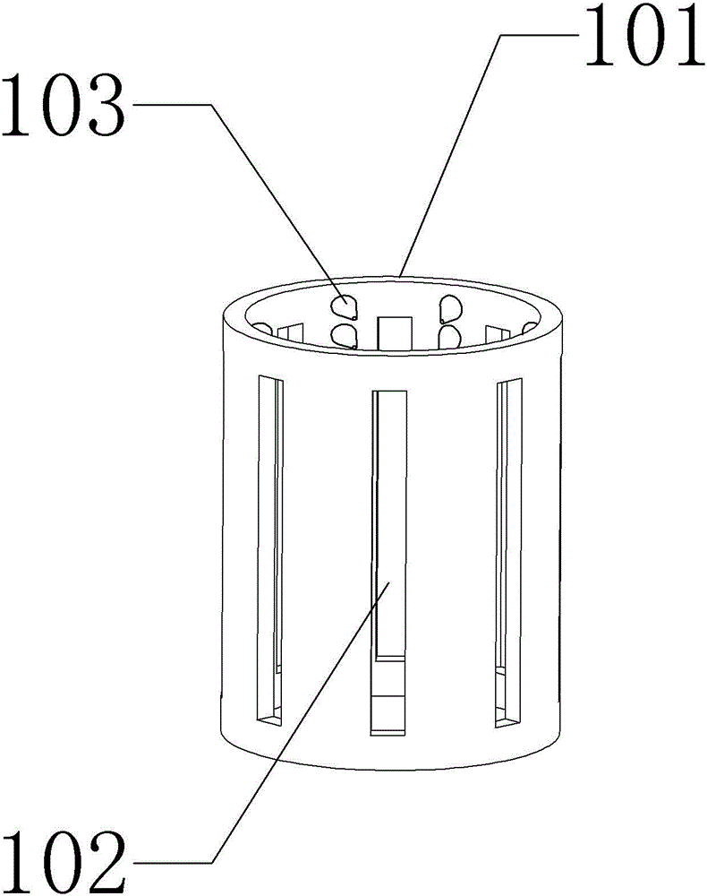
[0038] The difference between the present embodiment and the first embodiment is only the ear separating device, and other structures are basically the same as in the first embodiment. The ear separating device of the present embodiment includes a separation chamber, and the bottom of the separation chamber is connected with the upper opening of the ear box, and the separation There is a horizontal rotatable three-jaw elastic jaw 101 in the room. The three-jaw elastic jaw has three circumferentially evenly distributed jaws 102. The three-jaw elastic jaw is driven by the sprocket chain in the second transmission. The three-jaw elastic The inner diameter of the jaws is equivalent to the small head diameter of a single ear of corn.

Embodiment 3

[0040] The present embodiment differs from Embodiment 1 only in the beard and fringe separation device, and other structures are basically the same as in Embodiment 1. The beard and fringe separation device includes an inclined cylindrical conveying separation path 101, and the conveying and separation path 101 is driven by the second road. The sprocket chain in the chain drives the ratchet pawl mechanism, and the ratchet pawl mechanism vibrates back and forth during the conveying process. The front end of the conveying separation path 101 is connected with the upper opening of the ear box, and the side wall of the conveying separation path is provided with a plurality of axial A strip-shaped through hole 102, a strip-shaped guide hole is opened on the upper side wall of the conveying separation path, and a pendulum brush 103 that can reciprocate axially along the conveying separation path is arranged in the guide hole. The bristles have blades.


PUM


Abstract

The invention discloses a peeling-off mechanism of a corn harvesting machine, aiming at solving the problems in the prior art that a single steel roller has a small grasping force, the longitudinal motion resistance is great when a single rubber roller is adopted, and corn ears can slide easily when an arraying manner of driving rollers and driven rollers is adopted. The peeling-off mechanism of the corn harvesting machine comprises a plurality of groups of driving rollers and driven rollers, and the driving rollers and driven rollers are oppositely paired for peeling, and the peeling-off mechanism is characterized in that each group of the driving roller and driven roller are vertically staggered; W-shaped groove-shaped configuration is formed by each group of the driving roller and driven roller; a spiral steel bar section is arranged on the surface of the front half section of each group of the driving rollers, and a rubber roller section with a spiral groove is arranged on the surface of the rear half section of each group of the driving roller; and a square rubber bulge is arranged on the surface of each group of the driven roller.

Description

technical field [0001] The invention relates to an agricultural corn harvester, in particular to a peeling mechanism of the corn harvester. Background technique [0002] The corn harvester is an agricultural machine that completes multiple operations such as picking ears, stacking, and returning the stalks to the field at one time when the corn is mature. The main structure of the peeling mechanism of the corn harvester includes a walking chassis, a power mechanism and a cab arranged on the walking chassis, a header and a straw cutting device arranged in front of the walking chassis, a peeling machine and an ear box arranged behind the walking chassis. The peeling mechanism of the current corn harvester often has the following disadvantages: 1. Both the driving roller and the driven roller use a single steel roller or rubber roller. The single steel roller has a small gripping force, and the surface is easy to wear, which is not conducive to peeling , while the longitudinal...

Claims


Application Information

Patent Timeline
IPC IPC(8): A01D45/02A01F11/06
Inventor 刘友明
Owner CHONGQING SHUANGEN AGRI MACHINERY MFG
Why Eureka
Try Eureka