Novel rotary special-shaped polishing machine

A rotary, polishing machine technology, applied in surface polishing machine tools, grinding/polishing equipment, grinding/polishing safety devices, etc. The effect of enhanced flexibility and improved grinding accuracy

Active Publication Date: 2015-12-30
FOSHAN NANHAI FUDONG MACHINERY EQUIP
View PDF11 Cites 12 Cited by
  • Summary
  • Abstract
  • Description
  • Claims
  • Application Information

AI Technical Summary

Problems solved by technology

[0004] However, the above two board polishing machines can only process the flat surface of the board, and cannot polish the special-shaped grooves. For some decorative boards, especially the boards with special-shaped grooves on the surface, manual polishing is often required. Low and low machining accuracy

Method used


Image

  • Novel rotary special-shaped polishing machine
  • Novel rotary special-shaped polishing machine
  • Novel rotary special-shaped polishing machine

Examples


Embodiment 1

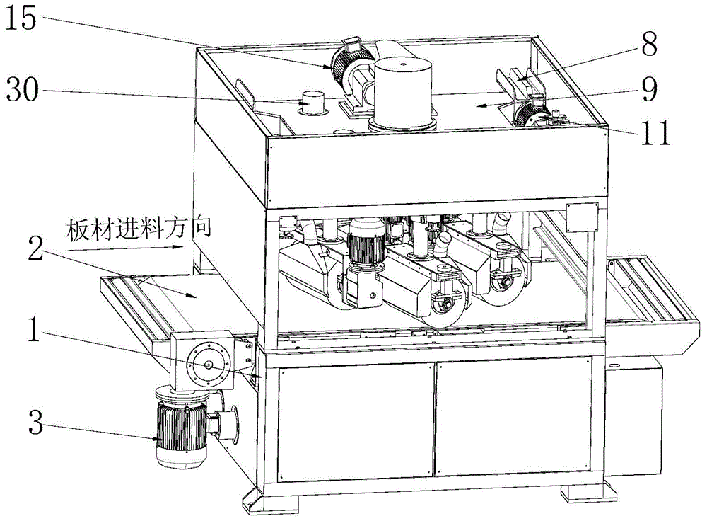
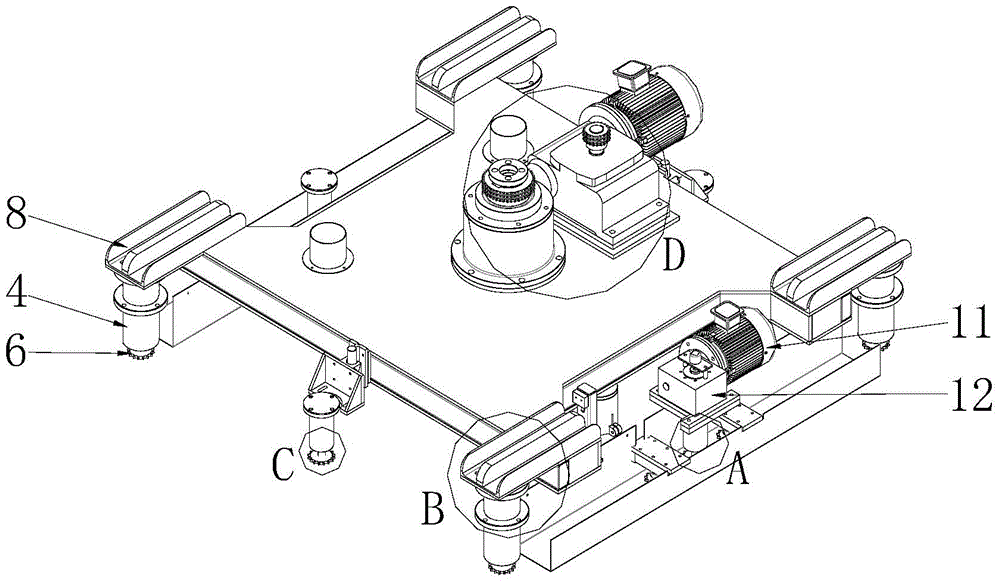
[0042] Such as Figure 1-5 In the polishing machine shown, a conveyor belt 2 as a transmission device is installed on the frame 1, and the conveyor belt 2 is driven by a conveying drive motor 3. Above the conveyor belt 2, 4 lifting guide columns 4 are also installed on the frame 1, and the lifting screw rod 5 that can be vertically lifted relative to the lifting guide column 4 is installed in each lifting guide column 4, and the end of the lifting screw rod 5 is installed with a The first driven sprocket 6 of the driven drive wheel and the top of the lifting screw 5 are equipped with a connecting flange 7, which is connected to the lifting platform 9 through a connecting block 8. In addition, several auxiliary guide columns 10 are installed on the frame 1, and the lifting screw 5 that can be vertically lifted relative to the auxiliary guide column 10 is also installed on the auxiliary guide column 10. The end of the lifting screw 5 is also installed with a first slave. Moving...

Embodiment 2

[0050] The difference between this embodiment 2 and embodiment 1 is that in this embodiment 2, if Figure 11 , 12 As shown, the frame 1 is also provided with a pressure roller 35 that can rotate relative to the frame 1. The pressure roller 35 is located upstream of the conveyor belt 2 to ensure that the position of the plate entering the polishing machine will not deviate. In addition, a linear guide rail 36 is installed on the frame 1 , and the guiding axis of the linear guide rail 36 is perpendicular to the conveying direction of the conveyor belt 2 . The two ends of the pressure roller 35 are connected with the slide block of the linear guide 36 . Utilizing the linear guide rail 36, the pressure roller 35 can be raised and lowered relative to the conveyor belt 2 to adapt to plates of different thicknesses. For the convenience of adjustment, an adjustment screw 43 can be installed on the slider, and a handle 44 can be installed at the end of the adjustment screw 43, so tha...

Embodiment 3

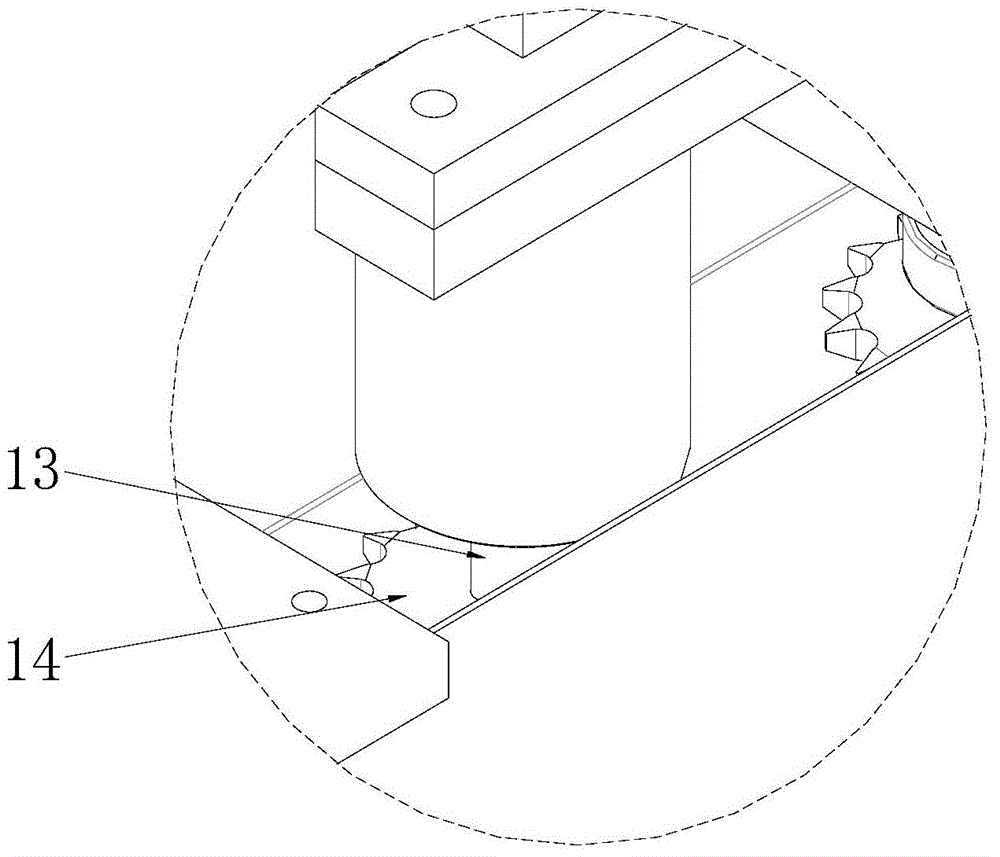
[0052] The difference between this embodiment 3 and embodiment 2 is that in this embodiment 3, if Figure 13-16 As shown, an anti-collision device is also installed on the frame 1, and the anti-collision device includes a baffle left fixture 37 installed on the frame 1, a baffle right fixture 38, and a baffle left fixture 37 and a baffle right fixture. 38 and a baffle 39 that can rotate relative to the frame 1, and the baffle 39 is formed with a blocking surface 40 that is inclined to the conveying direction of the transmission device. Such as Figure 14 , 15 As shown, a torsion spring 41 is also provided between the baffle plate 39 and the baffle plate left piece 37 , one end of the torsion spring 41 is fixed on the baffle plate left piece 37 , and the other end is attached to the baffle plate 39 . The distance between the lowest end of the baffle plate 39 and the conveyor belt 2 is equal to the distance between the polishing roller 29 and the conveyor belt 2 . When the pl...


PUM


Abstract

The invention discloses a novel rotary special-shaped polishing machine. The novel rotary special-shaped polishing machine comprises a rack. A conveying device for conveying boards is arranged on the rack. The rack is further provided with a rotary platform capable of rotating relative to the rack. The rotary platform is located above the conveying device. The rotary platform is provided with multiple polishing devices arranged around a rotary shaft of the rotary platform. The polishing devices comprise polishing rollers and polishing driving motors used for driving the polishing rollers to rotate automatically relative to the rotary platform. Multiple grinding wires formed by compounding resin and carborundum are arranged on the polishing rollers in the radial direction. Through revolution of the rotary platform and autorotation of the polishing rollers, special-shaped grooves in the boards can be effectively polished through the grinding wires on the polishing rollers; the grinding wires are formed by compounding resin and carborundum, so that the strength of the grinding wires is enhanced while the flexibility of the grinding wires is guaranteed, and grinding accuracy is greatly improved.

Description

technical field [0001] The invention relates to a plate polishing machine, in particular to a novel rotary special-shaped polishing machine. Background technique [0002] At present, the polishing and molding of planks is mainly completed by sanding with a woodworking planer. Usually, the polishing and molding of each plank must be processed repeatedly for several times to complete. In the field of wood deep processing technology, there is a great demand for polished and formed wood boards, especially under the conditions of mechanized production, higher requirements are put forward for the production efficiency and processing accuracy of wood board polished and formed. Existing polishing and forming processing equipment Can not meet the current market demand. [0003] In order to provide the production efficiency and processing accuracy of wood polishing and molding, technicians in the industry have conducted research on plate polishing machines, such as a wood polishing m...

Claims


Application Information

Patent Timeline
Patent Type & Authority Applications(China)
IPC IPC(8): B24B29/02B24B47/00B24B47/12B24B41/06B24B41/00B24B55/06B24B27/00
CPCB24B27/0076B24B29/02B24B41/005B24B41/06B24B47/00B24B47/12B24B55/06
Inventor 李永富
Owner FOSHAN NANHAI FUDONG MACHINERY EQUIP
Why Eureka
Try Eureka