Cooling tower shared by multiple systems of electric locomotive

An electric locomotive and multi-system technology, applied in locomotive, transformer/inductor cooling, cooling/ventilation/heating reconstruction, etc., can solve the problems of high total auxiliary power consumption, large locomotive space volume, and uncompact structure, etc., to achieve The effect of improving operating economy, reducing cleaning and maintenance, and reducing maintenance and operating costs

Active Publication Date: 2015-12-30
CRRC DALIAN INST CO LTD
View PDF7 Cites 3 Cited by
  • Summary
  • Abstract
  • Description
  • Claims
  • Application Information

AI Technical Summary

Problems solved by technology

[0002] At present, in the existing cooling technology for passenger electric locomotives, one electric locomotive uses two identical cooling devices to dissipate heat for the traction transformer, traction converter, and train power supply cabinet. Since the two sets of cooling devices are distributed, each cooling device requires The independent fan unit, radiator, load-bearing support frame, water pump, expansion tank, auxiliary oil tank, water system pipeline, oil system pipeline and other components are not compact in structure, occupying a large total volume of locomotive space, heavy total weight, and total auxiliary power High consumption and loud noise

Method used


Image

  • Cooling tower shared by multiple systems of electric locomotive
  • Cooling tower shared by multiple systems of electric locomotive

Examples


Embodiment Construction

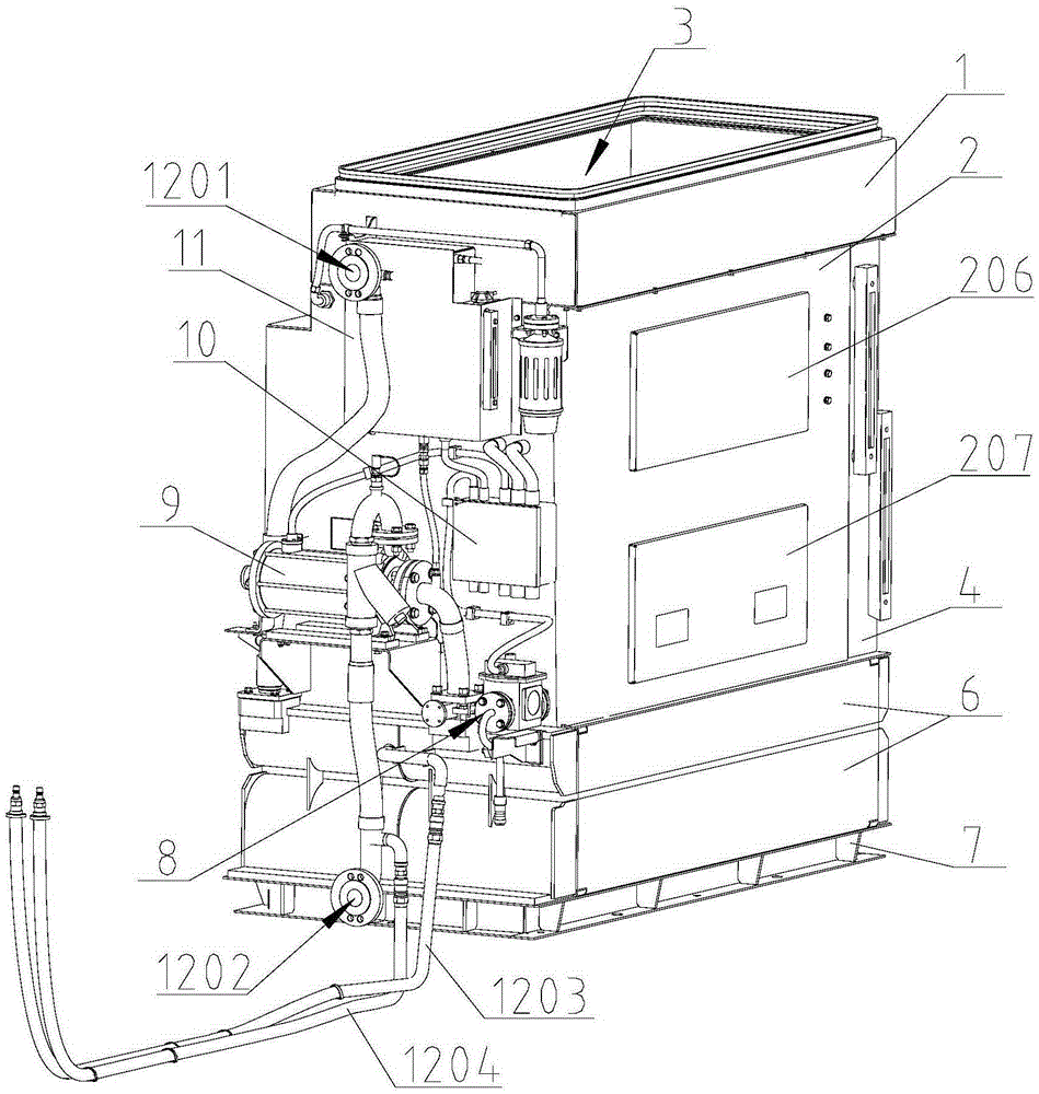
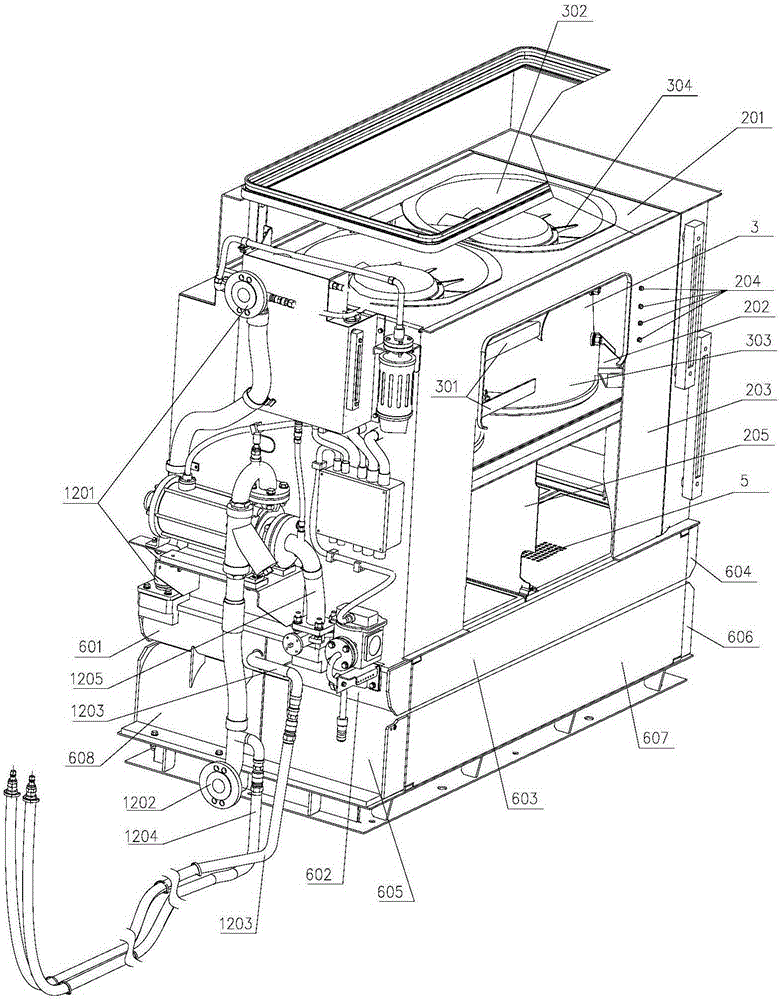
[0038] Such as figure 1 , figure 2 As shown, a cooling tower shared by multiple systems of an electric locomotive includes three cooling systems including a traction transformer cooling system, a traction converter cooling system, and a train power supply cabinet cooling system, specifically including a top air intake box 1, a middle box body 2, Double-row axial flow fan 3, air filter device 5, three-channel double-flow radiator 6, bottom bearing frame 7, water pump 9, expansion water tank 11, auxiliary oil tank 4, water pipeline (traction converter outlet pipe 1201, traction converter Water inlet pipe 1202, train power supply cabinet outlet pipe 1203, train power supply cabinet water inlet pipe 1204, water pump water inlet pipe 1205), oil pipeline, electrical connector 10, gas relay 8 and other components.

[0039] The top air intake box 1, the middle box body 2, the double-row axial flow fan 3, the air filter device 5, the three-channel double-flow radiator 6, and the bott...


PUM


Abstract

The invention discloses a cooling tower shared by multiple systems of an electric locomotive. The cooling tower comprises three cooling systems, namely a traction transformer cooling system, a traction current transformer cooling system and a train power supply cabinet cooling system, and specifically comprises a top air feeding box, a middle box body, two-column axial flow fan, an air filtering device, a three-runner double-flow-path heat dissipater, a bottom bearing framework, a water pump, an expansion water tank, a water pipeline, an auxiliary oil tank, an oil pipeline, an electric connector and a gas relay. By the adoption of an integrated complementary design method, the traction transformer, the traction current transformer and the train power supply cabinet cooling system are integrated in the same cooling tower; on the premise of simultaneously meeting the requirement on the heat dissipation of the traction transformer, the traction current transformer and the train power supply cabinet, the cooling tower disclosed by the invention has the advantages of compact structure, high heat dissipation performance, light weight, small volume, low auxiliary power consumption, low noise, convenient use and maintenance, high reliability and the like.

Description

technical field [0001] The invention relates to the technical field of heat exchange, in particular to a cooling tower shared by electric locomotive traction transformers, traction converters and train power supply cabinets, that is, a multi-system cooling tower for electric locomotives. Background technique [0002] At present, in the existing cooling technology for passenger electric locomotives, one electric locomotive uses two identical cooling devices to dissipate heat for the traction transformer, traction converter, and train power supply cabinet. Since the two sets of cooling devices are distributed, each cooling device requires The independent fan unit, radiator, load-bearing support frame, water pump, expansion tank, auxiliary oil tank, water system pipeline, oil system pipeline and other components are not compact in structure, occupying a large total volume of locomotive space, heavy total weight, and total auxiliary power High consumption and high noise. [000...

Claims


Application Information

Patent Timeline
IPC IPC(8): B61C17/00H01F27/12H05K7/20
Inventor 孔丽君贾红洋刘俊杰赵志强张震
Owner CRRC DALIAN INST CO LTD
Why Eureka
Try Eureka