Electric pneumatic breaking type rapid air charging device for replenishing compressed air

A technology of electro-pneumatic braking and compressed air, which is applied in the direction of braking transmission, pump/compressor arrangement, pneumatic brake, etc., and can solve the problem of not being able to provide enough compressed air to the brake cylinder, and the time for air charging cannot be effectively obtained. Problems such as shortening, the brake machine cannot produce enough braking force, etc.

Inactive Publication Date: 2015-12-30
UNIV OF JINAN
View PDF7 Cites 6 Cited by
  • Summary
  • Abstract
  • Description
  • Claims
  • Application Information

AI Technical Summary

Problems solved by technology

[0007] But, the deficiency of this brake machine of prior art is: when the train is running normally, the filling or exhausting of the brake main pipe is controlled by the locomotive, and when the brake main pipe is filled with wind, the compressed air will be distributed through each vehicle. Valves / control valves flow to the pressure and auxiliary cylinders of this vehicle
However, since each vehicle is only controlled by electric signals when the electro-pneumatic brake is charged, the main wind source required in the process of charging the air is still provided by the locomotive, and the role of the air cylinder is only for the purpose of cooperating with the electro-pneumatic brake. To ensure the consistency of the relief of the whole train, even if the relief cylinder is added, under the control of the electric signal, the auxiliary cylinder and the pressure cylinder of each vehicle can start to fill the air almost at the same time, but the capacity of the relief cylinder is small and The maximum pressure will not exceed the constant pressure of the brake main pipe, and it will only provide a small amount of wind for the brake main pipe. Most of the wind still needs to be provided by the locomotive, and the air filling time cannot be effectively shortened.
[0013] It can be seen that no matter whether it is an automatic air brake or an electro-pneumatic brake, after a relief, the pressure in the auxiliary air cylinder fails to return to the standard value in a short period of time, and the brake cannot be applied when braking is required. Cylinders provide enough compressed air that the brakes don't produce enough braking force, or even no braking effect at all

Method used


Image

  • Electric pneumatic breaking type rapid air charging device for replenishing compressed air
  • Electric pneumatic breaking type rapid air charging device for replenishing compressed air
  • Electric pneumatic breaking type rapid air charging device for replenishing compressed air

Examples


Embodiment 1

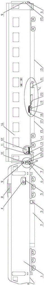
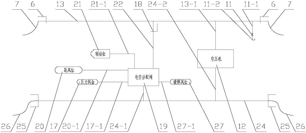
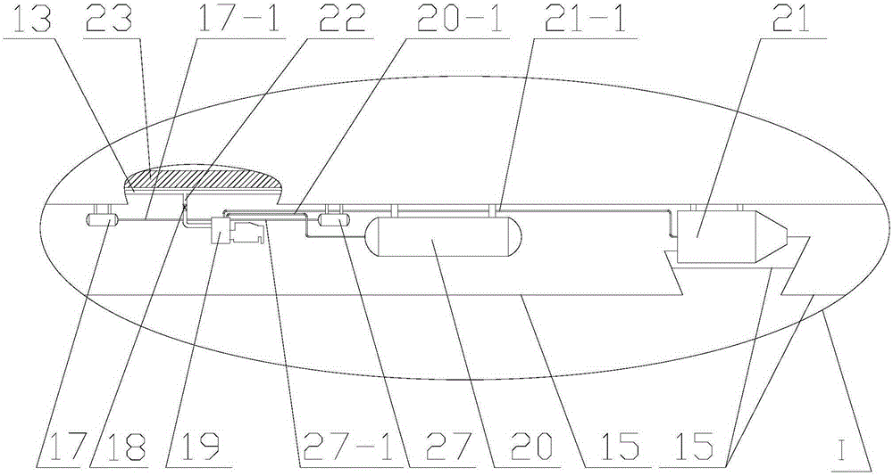
[0125] 1. The electro-pneumatic brake fast charging device for supplementing compressed air includes: locomotive body 1, fuel tank 2, main air cylinder 3, locomotive air compressor 4, locomotive floor 5, angled plug door 6, brake hose 7 , resistance cabinet vent 8, power connector A9, jumper wire A10, emergency valve 11, air compressor with stable output pressure 12, brake main pipe 13, bogie 14, foundation brake device 15, vehicle body 16, pressure Air cylinder 17, cut-off plug 18, electro-pneumatic distribution valve 19, auxiliary air cylinder 20, brake cylinder 21, brake branch pipe 22, vehicle bottom beam 23, control cable 24, power connector B25, jumper wire B26, wind relief Cylinder 27,

[0126] Emergency valve 11 includes: emergency brake pipe 11-1, emergency air outlet 11-2,

[0127] The air compressor 12 with stable output pressure includes: air filter 12-1, intake pipe 12-2, air compressor motor 12-3, motor support 12-4, air compressor body 12-5,

[0128] Brake mai...

Embodiment 2

[0164] Application of Electro-pneumatic Braking Rapid Air Filling Device Supplementing Compressed Air

[0165] 1. The electro-pneumatic brake fast charging device for supplementing compressed air includes: locomotive body 1, fuel tank 2, main air cylinder 3, locomotive air compressor 4, locomotive floor 5, angled plug door 6, brake hose 7 , resistance cabinet vent 8, power connector A9, jumper wire A10, emergency valve 11, air compressor with stable output pressure 12, brake main pipe 13, bogie 14, foundation brake device 15, vehicle body 16, pressure Air cylinder 17, cut-off plug 18, electro-pneumatic distribution valve 19, auxiliary air cylinder 20, brake cylinder 21, brake branch pipe 22, vehicle bottom beam 23, control cable 24, power connector B25, jumper wire B26, wind relief Cylinder 27,

[0166] Emergency valve 11 includes: emergency brake pipe 11-1, emergency air outlet 11-2,

[0167] The air compressor 12 with stable output pressure includes: air filter 12-1, intak...


PUM


Abstract

The invention relates to an electric pneumatic breaking type rapid air charging device for a replenishing compressed air. The electric pneumatic breaking type rapid air charging device is characterized in that two locomotive air compressors are connected in parallel and are connected with a total air cylinder; the total air cylinder is connected with a serial maneuvering device; the serial maneuvering device is connected with a braking main pipe; a relief air cylinder is connected with an electric pneumatic distribution valve through a relief air pipe; a control cable is connected with the electric pneumatic distribution valve through a branched control bypass A and is connected with an air compressor capable of stabilizing output pressure through a branched control bypass B; an air compressor body is connected with an air compressor motor, and a motor support seat is arranged under the air compressor motor; electric power connectors A are arranged at two ends of a locomotive or a vehicle; electric power connectors B are arranged at two ends of the locomotive or the vehicle; a bridging wire A is connected with the electric power connectors A of the locomotive and the vehicle or two adjacent vehicles; a bridging wire B is connected with the electric power connectors B of the locomotive and the vehicle or two adjacent vehicles; and the control cable is connected with the bridging wire B through the electric power connectors B at the joints of sections of the vehicle.

Description

technical field [0001] The utility model relates to an electro-pneumatic brake quick-filling device for supplementing compressed air, which relates to the technical field of vehicle brake relief. Background technique [0002] my country's railway network spreads all over the country, and railway passenger transport is the mainstream means of transportation. [0003] During my country's railway operation, at 4:41 on April 28, 2008, the downlink Beijing-Qingdao passenger train T195 derailed between Wangcun and Zhoucun on the Jiaoji Line and rushed to the outside of the uplink base. At this time, the normal operation of the 5034 passenger train from Yantai to Xuzhou failed to brake enough, and finally collided with the derailed vehicle at a speed of 70 kilometers per hour, and the locomotive and the 1st to 5th carriages derailed. The Jiaoji railway train collision accident has caused 72 deaths and 416 injuries. [0004] Therefore, the train braking response time is short, and...

Claims


Application Information

Patent Timeline
Patent Type & Authority Applications(China)
IPC IPC(8): B61H11/06B60T13/68B60T17/02
Inventor 马晶
Owner UNIV OF JINAN
Why Eureka
Try Eureka