
Turbine Driven Debris Bed Remover

A technology for removing devices and cuttings beds, which is applied in wellbore/well components, earthwork drilling, and flushing wellbore, etc. It can solve the problems of prone to accidents and high cost of cuttings removal, so as to ensure mechanical strength and improve cuttings Removal efficiency, the effect of preventing the formation of cuttings beds

Active Publication Date: 2017-11-10
NORTHEAST GASOLINEEUM UNIV
View PDF1 Cites 0 Cited by
  • Summary
  • Abstract
  • Description
  • Claims
  • Application Information

AI Technical Summary

Problems solved by technology

[0009] The purpose of the present invention is to provide a turbine-driven cuttings bed removal device, which is used to solve the problem of high cost of cuttings removal in wells with complex structures such as drilling horizontal wells, high-inclination wells, and extended-reach wells. Accident-Prone Problems

Method used


Image

  • Turbine Driven Debris Bed Remover
  • Turbine Driven Debris Bed Remover

Examples


Embodiment Construction

[0021] The present invention is described further below:

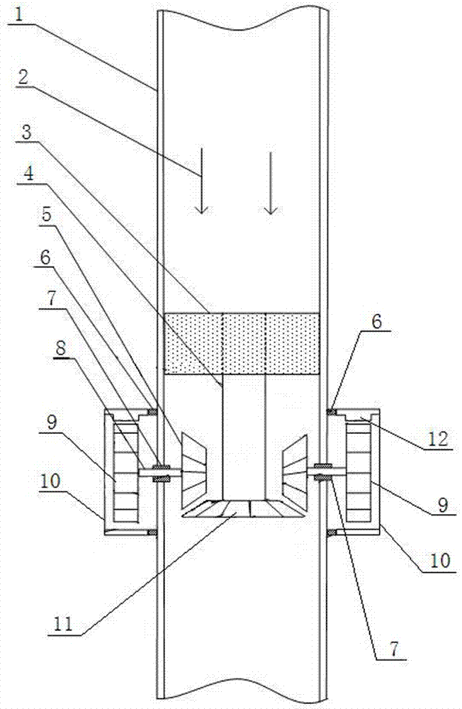
[0022] Such as figure 1 As shown, this turbine-driven debris bed removal device includes a turbine group 3, a transmission shaft 4, a driving bevel gear 11, a linkage bevel gear group, a turbulence generator 10, a turbine group 3, a transmission shaft 4, and a driving bevel gear. The gear 11 and the internal gear 5 of the linkage bevel gear set are all installed inside the drill pipe 1. The linkage bevel gear set is formed by connecting the internal gear 5 and the external gear 9 through the linkage shaft 8, and is fixed on the drill pipe through the linkage shaft 8 1, a sealed bearing 7 is arranged between the linkage shaft 8 and the drill pipe 1, the internal gear 5 is located in the drill pipe 1, and the external gear 9 is located in the turbulence generator 10. The turbine stator is directly fixed on the inner wall of the drill pipe 1, the turbine rotor is connected to the transmission shaft 4, and the lower end o...


PUM


Abstract

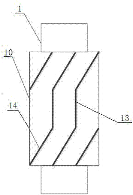
The present invention relates to a turbine-driven debris bed removal device, which comprises a turbine set, a transmission shaft, a driving bevel gear, a linkage bevel gear set, a sealed bearing, a turbulence generator, and a turbine set Installed in the drill pipe, the turbine stator is fixed on the inner wall of the drill pipe, the turbine rotor is connected to the transmission shaft, the lower end of the transmission shaft is connected to the driving bevel gear, the driving bevel gear meshes with the internal gear of the linkage bevel gear set, and the linkage bevel gear set The external gear of the turbulence generator meshes with the ring gear on the inner wall of the turbulence generator; the internal gear and the external gear of the linkage bevel gear set are connected by a linkage shaft, the internal gear is located in the drill pipe, and a sealed bearing is arranged between the linkage shaft and the drill pipe; The outer wall of the flow generator is provided with turbulence fins composed of straight tooth fins and helical tooth fins, and the turbulent flow generator is connected with the drill pipe through a sealed bearing. The invention can also carry out cuttings removal work in the drilling stop stage, which improves the cuttings removal efficiency and has low cost.

Description

technical field [0001] The invention relates to a cuttings cleaning tool in the process of oil and natural gas drilling, in particular to a turbine-driven cuttings bed removal device for wellbore cleaning when drilling horizontal wells, high-inclination wells, extended-reach wells and other complex-structured wells. Background technique [0002] When drilling horizontal wells, high-inclination wells, extended-reach wells, and wells with complex structures, the drill bit continuously breaks rocks to form cuttings particles. Cuttings beds are formed on the lower wellbore of wells with complex structures. Field experience and a large number of laboratory theoretical experiments have shown that cuttings beds are easy to form between highly deviated well sections and horizontal well sections (the inclination angle is about 45~90°). . If the cuttings bed deposited on the downhole wall is not properly removed and controlled, it will cause many serious problems in the drilling proc...

Claims


Application Information

Patent Timeline
Patent Type & Authority Patents(China)
IPC IPC(8): E21B21/00
Inventor 孙晓峰闫广平曲晶瑀张克博陈烨汤捷
Owner NORTHEAST GASOLINEEUM UNIV
Learn More