Novel floating heat exchanger equipment

A floating, heat exchanger technology, applied in the direction of mobile ducted heat exchangers, heat exchange equipment, heat exchanger types, etc., can solve the problem that the volume cannot be effectively utilized, the heat exchange effect cannot be achieved, and the heat transfer coefficient of the equipment is low. and other problems to achieve the effect of saving project cost, solving scale phenomenon and reducing equipment cost

Inactive Publication Date: 2015-12-30
WUXI HUISHAN HELI HEAT TRANSFER EQUIP FACTORY
View PDF5 Cites 2 Cited by
  • Summary
  • Abstract
  • Description
  • Claims
  • Application Information

AI Technical Summary

Problems solved by technology

[0003] At present, there are still many shortcomings in the floating heat exchangers on the market. For example, most heat exchangers on the market cannot effectively use the volume, resulting in a lot of waste, and most of the equipment has a low heat transfer coefficient, which leads to failure to achieve ideal The effect of heat exchange affects the actual work needs, and the scale condensation of heat transfer equipment in the market is serious, which is easy to cause dangerous accidents. Therefore, we propose a new type of floating heat exchanger equipment for the above problems

Method used


Image

  • Novel floating heat exchanger equipment

Examples


Embodiment

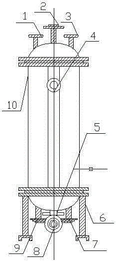
[0020] Example: such as figure 1 As shown, the present invention provides a new type of floating heat exchanger equipment, including a safety valve 1, a hot water port 2, a branch pipe interface 3, a pressure gauge 4, a water separation reactor 5, a support frame 6, and condensed water 7 Outlet, sewage outlet 8, steam inlet 9, shell 10; a safety valve 1 is set on the top of the shell 10 and the safety valve 1 is embedded in the surface of the shell 10; a hot water port 2 is set on one side of the safety valve 1, and the branch pipe interface 3 The hot water outlet 2 is symmetrically arranged with the safety valve 1; the bottom of the shell 10 is equipped with a sewage outlet 8 and a steam inlet 9 is installed on the side of the sewage outlet 8; the condensed water outlet 7 is located on the side of the sewage outlet 8 and the condensed water outlet 7 It is arranged symmetrically with the steam inlet 9; a water separation reactor 5 is installed on the top of the sewage outlet 8...


PUM


Abstract

The invention provides novel floating heat exchanger equipment. The novel floating heat exchanger equipment comprises a safety valve, a hot water opening, a branched pipe connector, a pressure gauge, a water-distribution reactor, supporting frames, a condensate outlet, a sewage discharging opening, a steam inlet and a shell. The safety valve is arranged at the top of the shell and embedded into the surface of the shell. The hot water opening is formed in one side of the safety valve, and the branched pipe connector and the safety valve are symmetrically arranged through the hot water opening. The sewage discharging opening is formed in the bottom of the shell, and the steam inlet is formed in one side of the sewage discharging opening. The condensate outlet is formed in one side of the sewage discharging opening, and the condensate outlet and the steam inlet are symmetrically formed. The water-distribution reactor is installed at the top of the sewage discharging opening, and one end of the water-distribution reactor is communicated with the shell. The pressure gauge is installed on the surface of the shell and connected with the interior of the shell. The supporting frames are installed at the bottom of the shell and symmetrically distributed on the two sides of the sewage discharging opening. The left and right symmetrical structure is adopted, design is simple, and installing and using are convenient.

Description

technical field [0001] The invention relates to a heat exchanger device, in particular to a floating heat exchanger device, which belongs to the application field of thermodynamic machinery. Background technique [0002] With the development of modern technology, floating heat exchangers are widely used in production, HVAC, and sanitary hot water systems. They are energy-saving products recommended by the country and can completely replace old-fashioned national standard heat exchangers. Vibration, the scale is not easy to adhere to the pipe wall, even if there is some scale, it is easy to fall off, and the significant difference in thermal expansion and contraction between copper and scale can be used to remove the scale by thermal shock. The shell of the floating heat exchanger is made of Carbon steel or stainless steel, the material of the heat exchange tube is copper, and the floating heat exchanger with special material, heat exchange area and working pressure level can...

Claims


Application Information

Patent Timeline
Patent Type & Authority Applications(China)
IPC IPC(8): F28D7/04F28D11/06F28G7/00F28F13/12
Inventor 是旺道
Owner WUXI HUISHAN HELI HEAT TRANSFER EQUIP FACTORY
Why Eureka
Try Eureka