
A long-distance buried oil and gas pipeline network electrical decoupling and segmentation method for defense against geomagnetic storm disasters

A technology for geomagnetic storms and oil and gas pipelines, applied in data processing applications, predictions, instruments, etc., can solve the problems of equipotential connector burnout, inability to change output polarity, overvoltage breakdown of insulating joints, etc.

Inactive Publication Date: 2018-11-30
CHINA UNIV OF PETROLEUM (BEIJING)
View PDF2 Cites 0 Cited by
  • Summary
  • Abstract
  • Description
  • Claims
  • Application Information

AI Technical Summary

Problems solved by technology

[0006] (2) When the high-voltage DC power transmission unit is operating on the ground, a large current flows in the nearby pipelines, causing the potentiostat to fail or even burn out, insulation joints over-voltage breakdown, equipotential connectors burnt and other pipeline accidents are commonly reported, while those caused by geomagnetic storms GIC is similar to DC transmission current, so too large GIC may also cause damage to equipment such as potentiostats
[0007] (3) The prior art potentiostat control has serious limitations
However, when the pipeline is too long, the global interference of the geomagnetic storm will cause the pipeline-ground potential to increase cumulatively with the increase of the pipeline length, and the stray current interference signals of the entire pipeline will be superimposed and "coupled", so that the original potentiostat loses Resistance to external stray current interference
Moreover, the existing potentiostat has a unipolar output, which cannot change the output polarity to adaptively eliminate external DC and AC stray current interference and geomagnetic stray current interference caused by space weather.

Method used


Image

  • A long-distance buried oil and gas pipeline network electrical decoupling and segmentation method for defense against geomagnetic storm disasters
  • A long-distance buried oil and gas pipeline network electrical decoupling and segmentation method for defense against geomagnetic storm disasters
  • A long-distance buried oil and gas pipeline network electrical decoupling and segmentation method for defense against geomagnetic storm disasters

Examples


Embodiment Construction

[0090] The present invention will be described in detail below in conjunction with the accompanying drawings and specific embodiments. The following description is only for demonstration and explanation, and does not limit the present invention in any form.

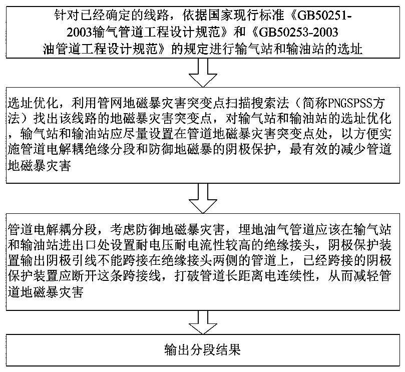
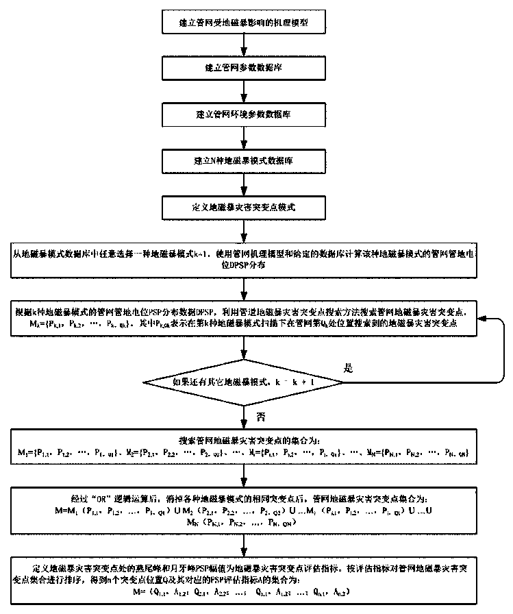
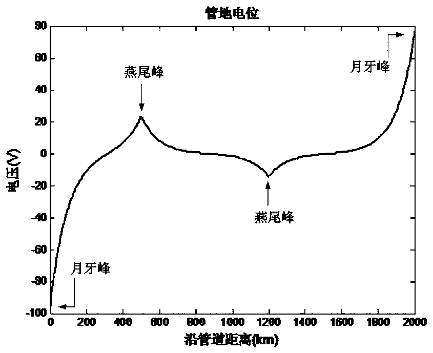
[0091] In order to reduce the sudden change point of pipeline geomagnetic storm disaster and reduce the "swallow tail peak" of pipeline PSP, thereby reducing the number of pipeline cathodic protection devices, and in order to reduce the degree of sudden change of PSP at pipeline geomagnetic storm disaster sudden change point, thereby greatly saving pipeline anti-corrosion costs, Improve the ability of buried oil and gas pipelines to defend against geomagnetic storm disasters, prolong the life of pipelines and related equipment, and design a long-distance buried oil and gas pipeline network electrical decoupling and segmentation method to prevent geomagnetic storm disasters, such as figure 1 As shown, the method includes fo...


PUM


Abstract

The invention relates to a long-distance buried oil and gas pipe network electrolytic coupling segmentation method for preventing geomagnetic storm disasters. The method comprises the steps that 1, aiming at a determined line, site selection of gas transmission stations and oil transmission stations is carried out according to the current standard; 2, geomagnetic storm disaster sudden change points of the line are found out through a pipe network geomagnetic storm disaster sudden change point scanning search method, and site selection optimization is carried out; 3, pipeline electrolytic coupling segmentation is carried out; 4, a segmentation result is output. According to the long-distance buried oil and gas pipe network electrolytic coupling segmentation method for preventing the geomagnetic storm disasters, geomagnetic induction current (GIC) and the pipe-to-soil potential (PSP) negative accumulation effect generated by the geomagnetic storm disasters in a long-distance electrical continuous buried oil and gas pipe network can be reduced, cathodic protection on a short-distance buried oil and gas pipeline can be further implemented, the capacity for the buried oil and gas pipeline to prevent the geomagnetic storm disasters is improved, and the service life of the pipeline and related equipment is prolonged.

Description

technical field [0001] The invention relates to the technical field of buried oil and gas pipeline network protection, in particular to an electrical decoupling and segmentation method for long-distance buried oil and gas pipeline network for preventing geomagnetic storm disasters. Background technique [0002] Long-distance oil and gas pipelines have gas stations and oil stations at intervals, and insulating flanges are installed at the inlet and outlet of the gas stations and oil stations to electrically isolate the pipelines. For the convenience of power supply and maintenance, pipeline cathodic protection devices It is installed at the gas transmission station and the oil transmission station, and the two sections of pipelines outside the insulating flanges of the gas transmission station and the oil transmission station are connected together with metal wires. After the gas transmission station and the oil transmission station of the entire pipeline are done like this ,...

Claims


Application Information

Patent Timeline
Patent Type & Authority Patents(China)
IPC IPC(8): G06Q10/04G06Q50/06
Inventor 梁志珊夏鹏程张举丘
Owner CHINA UNIV OF PETROLEUM (BEIJING)
Learn More