Printed unipolar folded oscillator log periodic antenna

A technology of logarithmic periodic antenna and folded oscillator, applied in the field of wireless communication, can solve the problem of large size, and achieve the effect of wide bandwidth, easy integration and low profile

Active Publication Date: 2015-12-30
HARBIN INST OF TECH
View PDF6 Cites 11 Cited by
  • Summary
  • Abstract
  • Description
  • Claims
  • Application Information

AI Technical Summary

Problems solved by technology

[0003] In order to solve the problem that the size of the ordinary printed logarithmic periodic antenna is too

Method used


Image

  • Printed unipolar folded oscillator log periodic antenna
  • Printed unipolar folded oscillator log periodic antenna
  • Printed unipolar folded oscillator log periodic antenna

Examples


specific Embodiment approach 1

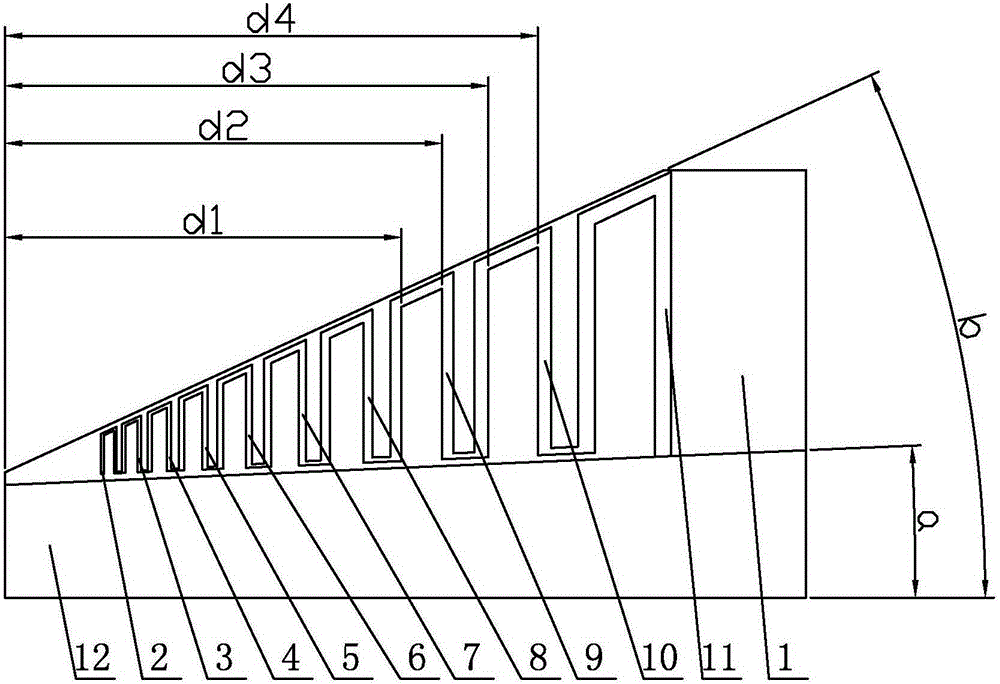
[0007] Specific implementation mode one: combine figure 1 and figure 2 Describe this embodiment. The printed monopole folded vibrator logarithmic periodic antenna described in this embodiment includes a dielectric substrate 1, a first inverted U-shaped microstrip line 2 on the front, a second inverted U-shaped microstrip line 3 on the front, and a third inverted U-shaped microstrip line on the front. Inverted U-shaped microstrip line 4, front fourth inverted U-shaped microstrip line 5, front fifth inverted U-shaped microstrip line 6, front sixth inverted U-shaped microstrip line 7, front seventh inverted U-shaped microstrip line 8. The eighth inverted U-shaped microstrip line on the front side 9, the ninth inverted U-shaped microstrip line on the front side 10, the tenth inverted U-shaped microstrip line on the front side 11, the strip-shaped microstrip line 12 on the front side, and the first strip-shaped microstrip line on the back side line 13 and the second strip microst...

specific Embodiment approach 2

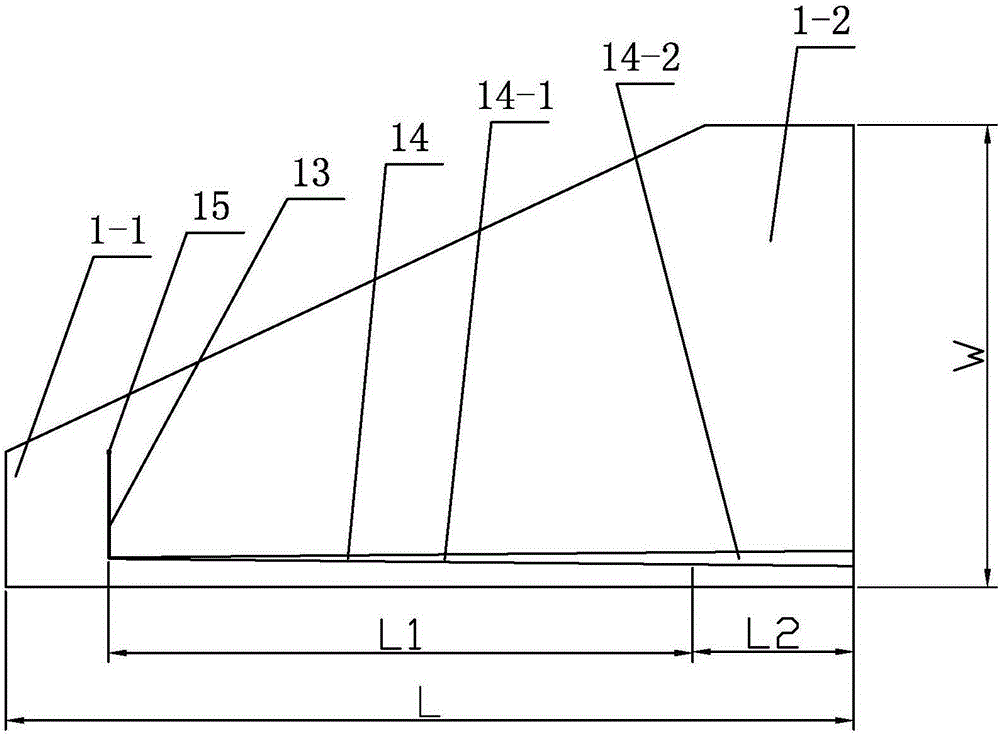
[0008] Specific implementation mode two: combination figure 1 and figure 2 To illustrate this embodiment, the length L of the dielectric substrate 1 of the printed monopole folded vibrator logarithmic periodic antenna described in this embodiment is 241.3 mm, the width W of the dielectric substrate 1 is 131 mm, and the thickness of the dielectric substrate 1 is 1.5 mm. The dielectric constant is 2.5-2.6.

[0009] The technical effect of this embodiment is: such an arrangement enables the antenna to have a smaller size while satisfying a given working frequency band. Other components and connections are the same as those in the first embodiment.

specific Embodiment approach 3

[0010] Specific implementation mode three: combination figure 1 and figure 2 Describe this embodiment, the angle b between the hypotenuse and the right-angled side of the right-angled trapezoidal plate 1-1 of the printed monopole folded oscillator log-periodic antenna described in this embodiment is 25°, and the two sides of the front strip microstrip line 12 The angle a between two long sides is 2.5°, the length of the first strip microstrip line 13 on the back is 30mm, and the second strip microstrip line 14 on the back is composed of the first section 14-1 and the second section 14-2, The length of the first section 14-1 is L1 is 171mm, the length L2 of the second section 14-2 is 40mm, the width of the second section 14-2 is 4mm, the first microstrip line 13 on the back and the second strip line on the back The U-shaped microstrip line 14 is connected by an arc, the radius of the arc is 0.5mm, the radius of the metallized via hole 15 is 0.4mm, the left vertical edge of th...


PUM

PropertyMeasurementUnit
Lengthaaaaaaaaaa
Widthaaaaaaaaaa
Thicknessaaaaaaaaaa

Abstract

The invention provides a printed unipolar folded oscillator log periodic antenna, relates to a log periodic antenna, particularly relates to the printed unipolar folded oscillator log periodic antenna, and aims at solving problems that a common printed log periodic antenna is oversized. The printed unipolar folded oscillator log periodic antenna comprises a dielectric substrate, a front surface first inverted U-shaped microstrip line, a front surface second inverted U-shaped microstrip line, a front surface third inverted U-shaped microstrip line, a front surface fourth inverted U-shaped microstrip line, a front surface fifth inverted U-shaped microstrip line, a front surface sixth inverted U-shaped microstrip line, a front surface seventh inverted U-shaped microstrip line, a front surface eighth inverted U-shaped microstrip line, a front surface ninth inverted U-shaped microstrip line, a front surface tenth inverted U-shaped microstrip line, a front surface strip-shaped microstrip line, a back surface first strip-shaped microstrip line and a back surface second strip-shaped microstrip line. The printed unipolar folded oscillator log periodic antenna is used for the field of wireless communication.

Description

technical field [0001] The invention relates to a logarithmic periodic antenna, in particular to a printed monopole folded vibrator logarithmic periodic antenna, which belongs to the field of wireless communication. Background technique [0002] The log-periodic antenna is a traditional broadband antenna, which has the advantages of wide impedance bandwidth, high in-band gain, and low sidelobe, and has become a research hotspot. With the help of printed circuit technology, the log-periodic antenna can be realized on a planar structure, and its low-cost mass production becomes possible. However, since modern communication and electronic systems tend to be more and more miniaturized, the size of the common printed logarithmic periodic antenna is too large, which greatly restricts its application. Contents of the invention [0003] In order to solve the problem that the size of the common printed logarithmic periodic antenna is too large, the present invention further propos...

Claims


Application Information

Patent Timeline
IPC IPC(8): H01Q1/38
Inventor 赵志华臧语章林澍刘冠君王蕾
Owner HARBIN INST OF TECH
Why Eureka
Try Eureka