Fluid conveying pipeline surface coating removing mechanical arm

A surface coating and fluid pipeline technology, applied in the field of surface coating removal manipulators for fluid conveying pipelines, can solve the problems of time-consuming, high coating bonding strength and labor, and achieve the effect of increasing stability and cleaning thoroughly.

Inactive Publication Date: 2016-01-06
SHENYANG JIANZHU UNIVERSITY
View PDF7 Cites 8 Cited by
  • Summary
  • Abstract
  • Description
  • Claims
  • Application Information

AI Technical Summary

Problems solved by technology

At present, such work is mainly done by workers holding angle grinders. Due to the high bonding strength of the coating, for example, the peel strength of three layers of polyethylene is greater than 100N / cm 2 ,Manual removal is not only time-consuming and laborious, but also the removal effect is not good

Method used


Image

  • Fluid conveying pipeline surface coating removing mechanical arm
  • Fluid conveying pipeline surface coating removing mechanical arm
  • Fluid conveying pipeline surface coating removing mechanical arm

Examples


Embodiment

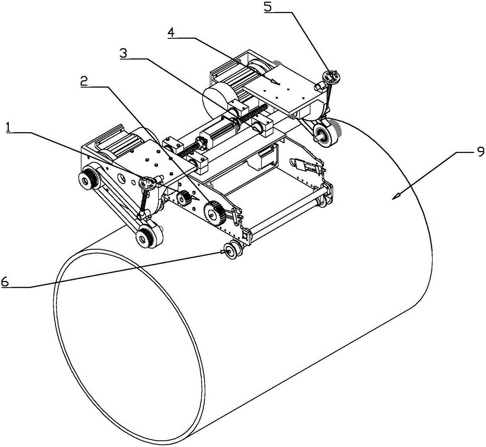
[0037] Example: such as figure 1 As shown, the present invention includes a bracket 1, a chain elastic adjustment device 2, a lateral adjustment device 3, an actuator 4, a pressure adjustment device 5 and a running mechanism 6, and the lateral adjustment device 3 is placed on the top plate 103 of the bracket 1, and the two actuators 4 is symmetrically connected to both ends of the lateral adjustment device 3, and the pressure adjustment device 5 is connected to the outside of the two actuators 4. The chain tension adjustment device 2 is set on the strip groove of the side plate 101 of the bracket, and the running mechanism 6 is connected to the side plate of the bracket. 101 on.

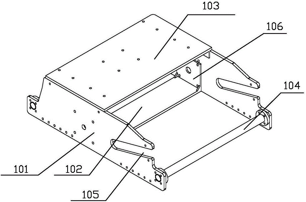
[0038] Such as figure 2 As shown, the bracket 1 includes a top plate 103, a bottom plate 102, two side plates 101 and a cylindrical bar 104, and the top and bottom ends of the two side plates 101 are respectively connected to the top plate 103 and the bottom plate 102 to form a supporting frame. E...

Embodiment 2

[0048] Embodiment 2: The difference between this embodiment and Embodiment 1 is that the open end of the long groove 105 on the side plate in this embodiment is higher than the closed end, and the angle α between it and the horizontal plane is 20 degrees.

Embodiment 3

[0049] Embodiment 3: The difference between this embodiment and Embodiment 1 is that the open end of the long groove 105 on the side plate in this embodiment is higher than the closed end, and the angle α between it and the horizontal plane is 25 degrees.


PUM


Abstract

The invention provides a fluid conveying pipeline surface coating removing mechanical arm and belongs to the technical field of pipeline removing instruments. The mechanical arm comprises a support, chain tightness degree adjusting devices, a transverse adjusting device, execution mechanisms, pressure adjusting devices and a traveling mechanism. The transverse adjusting device is arranged on a top plate of the support. The two execution mechanisms are symmetrically connected to the two ends of the transverse adjusting device. The pressure adjusting devices are connected to the outer sides of the two execution mechanisms. The chain tightness degree adjusting devices are arranged on strip-shaped grooves in side plates of the support. The traveling mechanism is connected to the side plates of the support. The mechanical arm can adapt to needs of different pipelines under different environment conditions; moreover, chain mass is low, the length can be decided freely according to the different use conditions, and workers can carry out disassembling and assembling conveniently; balancing performance of the whole mechanical arm is good, working efficiency is high, and the working range is expanded; synchronous belts are adopted for driving steel brushes to rotate, the transmission ratio is accurate, acting force on shafts is small, and the mechanical arm is compact in structure, good in oil and abrasion resistance, and good in aging-resistant performance.

Description

technical field [0001] The invention belongs to the technical field of pipeline cleaning equipment, in particular to a manipulator for cleaning the surface coating of fluid delivery pipelines. Background technique [0002] When oil and natural gas pipelines leak, it is necessary to remove the anti-corrosion coating on the surface of the pipeline, and then carry out plugging treatment. In China, using an angle grinder to remove the coating on the surface of the pipeline is the main technical means. At present, such work is mainly done by workers holding angle grinders. Due to the high bonding strength of the coating, for example, the peel strength of three layers of polyethylene is greater than 100N / cm 2 , Manual removal is not only time-consuming and laborious, but also the removal effect is not good. Contents of the invention [0003] In view of the above-mentioned technical problems, the present invention provides a manipulator for removing the coating on the surface o...

Claims


Application Information

Patent Timeline
Patent Type & Authority Applications(China)
IPC IPC(8): B08B9/023B24B27/033
CPCB08B1/04B08B9/023B24B27/033
Inventor 王丹李斌王帅赵强
Owner SHENYANG JIANZHU UNIVERSITY
Why Eureka
Try Eureka