Sealed pipe welding gun

A technology of pipe welding and welding torch, applied in the field of nuclear power plant engineering, can solve problems such as poor welding quality, and achieve the effect of improving stability and welding effect

Inactive Publication Date: 2016-01-06
CHINA GENERAL NUCLEAR POWER OPERATION +2
View PDF5 Cites 15 Cited by
  • Summary
  • Abstract
  • Description
  • Claims
  • Application Information

AI Technical Summary

Problems solved by technology

[0004] The main purpose of the present invention is to provide a closed pipe welding torch, which aims to solve the technical problem that the existing open welding easily leads to poor welding quality

Method used


Image

  • Sealed pipe welding gun
  • Sealed pipe welding gun
  • Sealed pipe welding gun

Examples


Embodiment Construction

[0033] It should be understood that the specific embodiments described here are only used to explain the present invention, not to limit the present invention.

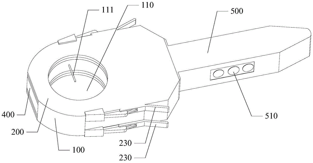
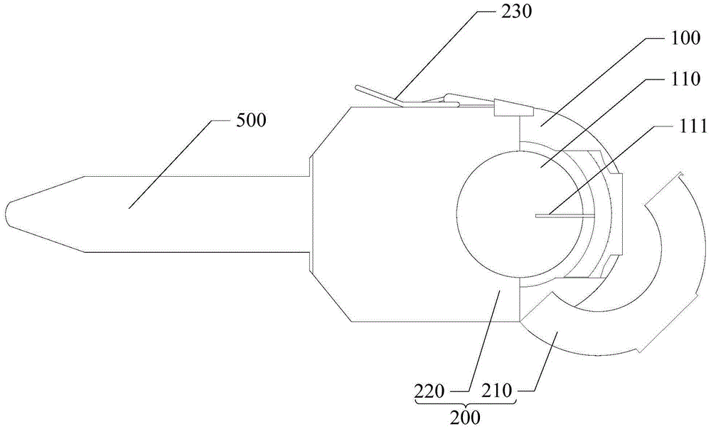
[0034] The invention provides a closed pipe welding torch, see figure 1 and figure 2 , in one embodiment, the closed tube welding torch includes a welding torch body 100 and clamping devices 200 arranged on opposite sides of the welding torch body 100, that is, the two clamping devices 200 clamp the welding torch body 100, and clamp The device 200 and the welding torch body 100 are connected and fixed by screws.

[0035] Wherein, the welding torch body 100 is provided with a welding chamber 110 that runs through its opposite sides for accommodating the pipe to be welded, communicates with the welding chamber 110 for the entrance and exit of the pipe to be welded to enter and exit the welding chamber 110, and supplies shielding gas. A gas passage into the welding chamber 110 . In actual application, the geometric s...


PUM


Abstract

The invention discloses a sealed pipe welding gun which comprises a welding gun body and clamping devices. The welding gun body is provided with a welding chamber penetrating the two opposite sides of the welding gun body, a passageway which is communicated with the welding chamber and through which a pipe to be welded enters and exits out of the welding chamber and a gas channel through which protective gas flows into the welding chamber. At least one welding electrode capable of rotating around a rotary shaft is arranged in the welding chamber. The welding gun body is further provided with a drive device for driving the welding electrodes to rotate. The clamping devices comprise upper clamps and lower clamps. Upper semicircular grooves are formed in the end faces of the upper clamps. Lower semicircular grooves corresponding to the upper semicircular grooves are formed in the end faces of the lower clamps. When the upper clamps and the lower clamps are closed, a clamping space used for clamping the pipe to be welded is formed by the upper semicircular grooves and the lower semicircular grooves in a matched manner and the upper clamps are combined with the pipe to be welded, the lower clamps and the welding gun body to seal the welding chamber. Therefore, the stability of welding arcs and the welding effect are greatly improved.

Description

technical field [0001] The invention relates to the technical field of nuclear power plant engineering, in particular to a sealed pipe welding torch. Background technique [0002] In active nuclear power plants, the pressure of the cooling water in the primary circuit is maintained by a voltage stabilizer. There are multiple electric heaters installed at the bottom of the voltage stabilizer. When the pressure drops, the system will start the electric heater to increase the steam to maintain the pressure. Stablize. When the pressure in the pressurizer is too high or too low, the reactor will automatically shut down, so the working stability and reliability of the pressurizer play a vital role in the safe operation of the nuclear power plant. During the service period of the nuclear power plant, the electric heater needs to be inspected and maintained regularly. If the electric heater is found to be damaged, the casing sleeve outside the electric heater should be cut to repla...

Claims


Application Information

Patent Timeline
Patent Type & Authority Applications(China)
IPC IPC(8): B23K9/28B23K9/26B23K9/32B23K9/12B23K37/053
CPCB23K9/28B23K9/12B23K9/26B23K9/32B23K37/003B23K37/053
Inventor 陈英杰王松刘超李杰冯兴旺郑孝纲颜少华邱永生黄开凯
Owner CHINA GENERAL NUCLEAR POWER OPERATION
Why Eureka
Try Eureka