Self-pressurizing device for automotive liquefied natural gas cylinder

A liquefied natural gas, self-pressurization technology, applied in pressure vessels, fixed-capacity gas storage tanks, gas/liquid distribution and storage, etc., can solve problems such as pressure drop in the bottle, no emergency shut-off valve device protection, and small flow rate of the vaporizer , to stabilize the pressure inside the gas cylinder, reduce heat leakage, and improve the effect of heat insulation performance

Inactive Publication Date: 2016-01-06
江南工业集团有限公司
View PDF8 Cites 3 Cited by
  • Summary
  • Abstract
  • Description
  • Claims
  • Application Information

AI Technical Summary

Problems solved by technology

At the same time, the driving force of boosting depends on the weight of the liquid in the bottle, and the liquid has to overcome the pressure resistance of the pipeline, so the power to drive the liquid flow is not enough, resulting in a small flow through the vaporizer, insufficient vaporization, and a longer boosting time , the pressurization is not stable and continuous; and the car is moving, the gas flowing into the upper part of the cylinder is condensed into liquid, and the pressure in the cylinder is further reduced; in addition, the pressurized liquid outlet pipe is a separate lead from the cylinder The root pipeline is exposed to the outside of the bottle without the protection of an emergency shut-off valve device, such as Chinese patent CN201120522081.3, once the pressurized liquid outlet pipeline is broken, a large amount of liquid will be vaporized after spraying out, and fire and explosion will occur when encountering an open flame. a great security risk

Method used


Image

  • Self-pressurizing device for automotive liquefied natural gas cylinder

Examples


Embodiment Construction

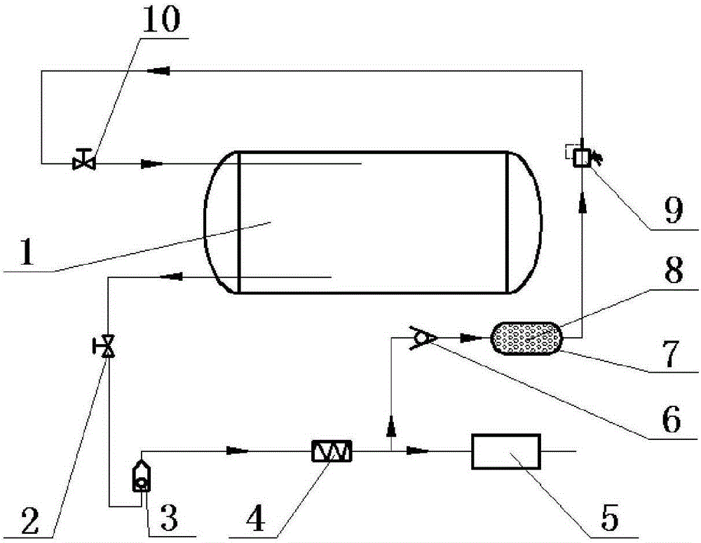
[0020] A self-pressurizing device for liquefied natural gas cylinders for vehicles, such as figure 1 Said, including vehicle liquefied natural gas cylinder 1, liquid outlet shut-off valve 2, emergency shut-off valve 3, carburetor 4, one-way valve 6, adsorption gas storage device 7, adsorbent 8, booster valve 9, gas phase shut-off valve 10 .

[0021] The liquefied natural gas cylinder 1 for vehicles communicates with the liquid outlet stop valve 2 and the gas phase stop valve 10 through pipelines.

[0022] Liquid outlet cut-off valve 2, emergency cut-off valve 3, vaporizer 4, one-way valve 6, adsorption gas storage device 7, booster valve 9, and gas phase cut-off valve 10 are sequentially connected in series on the pipeline.

[0023] The carburetor 4 communicates with the one-way valve 6 and the engine system 5 through pipelines respectively.

[0024] The adsorption gas storage device 7 is filled with an adsorbent 8 .

[0025] The working principle of the present invention i...


PUM


Abstract

The invention discloses a self-pressurizing device for an automotive liquefied natural gas cylinder. The gas cylinder self-pressurizing device comprises an automotive liquefied natural gas cylinder, a liquid outlet stop valve, an emergent cut-off valve, a vaporizer, a check valve and a pressurizing valve and further comprises an absorption gas storage device and a gas phase stop valve, wherein the automotive liquefied natural gas cylinder is provided with a liquid outlet connector and a gas inlet connector, and the liquid outlet connector, the liquid outlet stop valve, the emergent cut-off valve and the vaporizer are sequentially communicated in series through pipelines; an outlet of the vaporizer is connected with two pipelines, one pipeline is communicated with an engine system, and the other pipeline is sequentially communicated with the check valve, the absorption gas storage device, the pressurizing valve, the gas phase stop valve and the gas inlet connector in series; and when the pressure of gas in the automotive liquefied natural gas cylinder is higher than the set pressure of the check valve, the check valve is opened. The self-pressurizing device can automatically pressurize the gas cylinder rapidly, continuously and stably in the running process of an automobile and accordingly supply certain-pressure fuel to the engine system uninterruptedly so as to achieve the purpose of ensuring automobile safe and stable running.

Description

technical field [0001] The invention relates to a self-pressurizing device for liquefied natural gas cylinders for vehicles. Background technique [0002] The liquefied natural gas cylinders for automobiles are the fuel storage equipment for low-temperature liquefied natural gas vehicles. Only when the cylinders provide a stable fuel supply for the engine system can the vehicles run stably. This steady supply of fuel is accomplished by pressurizing the gas cylinders to ensure a steady delivery of fuel. [0003] The self-pressurization system commonly used at present is to discharge the liquefied natural gas in the gas cylinder through the pressurized liquid outlet pipe, and then return to the gas phase space of the gas cylinder after being vaporized by the air bath vaporizer to achieve the purpose of supercharging. However, as the cylinder continues to deliver fuel to the engine system, the liquid level in the cylinder decreases, the gas phase space increases, and the press...

Claims


Application Information

Patent Timeline
Patent Type & Authority Applications(China)
IPC IPC(8): F17C7/04F17C13/02F17C13/04F17C13/12
Inventor 魏贞闵李存礼易文吴金双杨哲韩鹏飞江山杨鹏
Owner 江南工业集团有限公司
Why Eureka
Try Eureka