Multi-source information fusion based high precision motion track detection system

A technology of multi-source information fusion and motion trajectory, which is applied in the direction of measuring devices, surveying and navigation, instruments, etc., can solve the problems of not improving the accuracy and dimension of target positioning and tracking, low positioning accuracy, and a single amount of information, and achieve high stability and fast motion detection, enhanced reliability and robustness, improved accuracy and dimensionality

Active Publication Date: 2016-01-06
QUANZHOU INST OF EQUIP MFG
View PDF5 Cites 62 Cited by
  • Summary
  • Abstract
  • Description
  • Claims
  • Application Information

AI Technical Summary

Problems solved by technology

The electromagnetic positioning system detects the three-dimensional magnetic field intensity of the permanent magnet or electromagnetic coil in space through the magnetic sensor array, and then iteratively solves the spatial position and attitude information of the permanent magnet or electromagnetic coil. NDI's electromagnetic positioning system uses two The vertically placed 3-axis electromagnetic induction coil realizes complete 6-axis motion detection, but the electromagnetic positioning system is susceptible to interference from environmental electromagnetic waves and ferromagnetic substances, which is unavoidable in industrial environments; VICON motion capture system based on optical positioning technology It consists of an infrared high-speed camera, a data processor and supporting application software. The infrared high-speed camera captures passive luminous marking points, and uses the principle of machine vision and laser scanning technology to realize the measurement of moving position information, but the optical positioning system can only measure marking points. spatial location information, and is easily affected by occlusion and ambient light and b

Method used


Image

  • Multi-source information fusion based high precision motion track detection system
  • Multi-source information fusion based high precision motion track detection system
  • Multi-source information fusion based high precision motion track detection system

Examples


Embodiment Construction

[0039] The present invention will be described in detail below in conjunction with specific embodiments. The following examples will help those skilled in the art to further understand the present invention, but do not limit the present invention in any form. It should be noted that those skilled in the art can make several modifications and improvements without departing from the concept of the present invention. These all belong to the protection scope of the present invention.

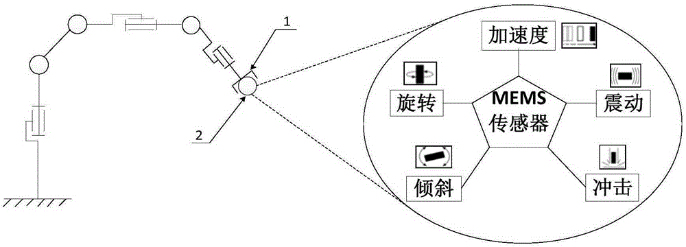
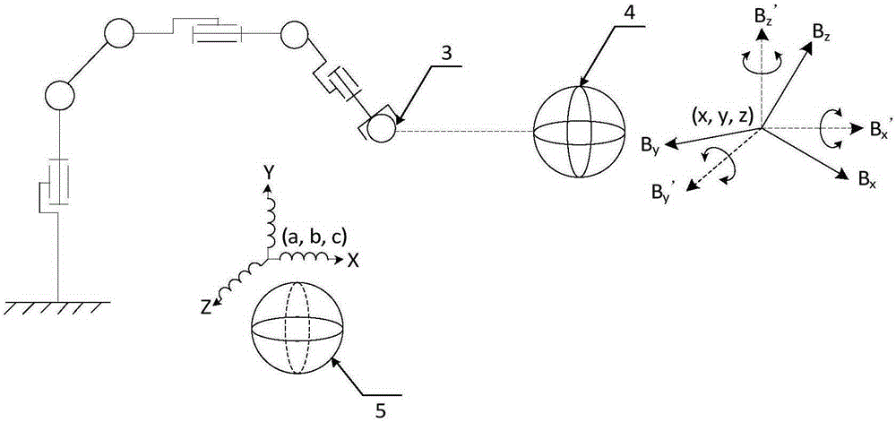
[0040] Taking the end of the flange plate of the mechanical arm as the moving part for measurement, the detailed embodiments of the present invention will be described in conjunction with the accompanying drawings.

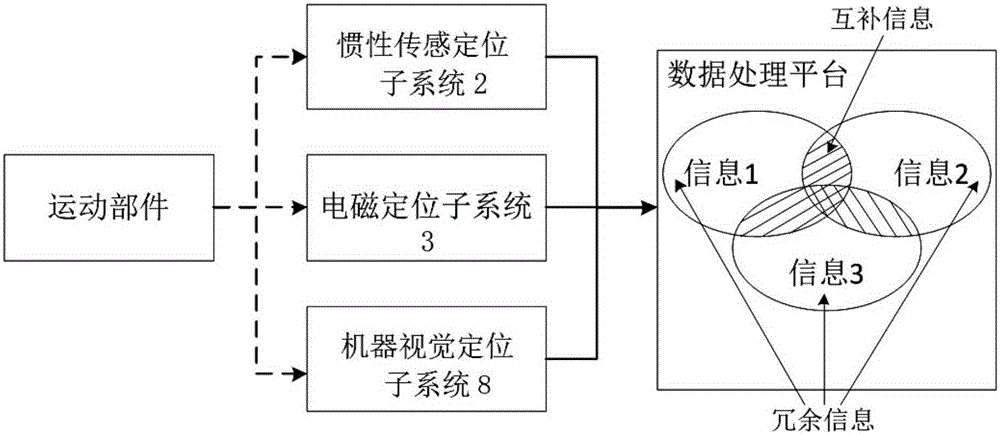
[0041] Such as figure 1 As shown, a high-precision motion trajectory detection system based on multi-source information fusion, the system consists of three modular subsystems of inertial sensor positioning subsystem 2, electromagnetic positioning subsystem 3 and machine vision positi...


PUM


Abstract

The invention provides a multi-source information fusion based high precision motion track detection system, which includes inertial sensor positioning, machine vision positioning and electromagnetic positioning three subsystems and a data processing platform, wherein the inertial sensor positioning subsystem is used for three-dimensional attitude angle measurement; the electromagnetic positioning subsystem is used for measuring three-dimensional position and three-dimensional attitude information; the machine vision positioning subsystem is used for measuring three-dimensional position information; and the data processing platform performs comprehensive analysis and coordination processing on the multi-source information acquired by the subsystems, carries out coordinate transformation on data and data correction, data association and state estimation fusion based on a distributed state fusion structure model, and realizes six-dimensional pose dynamic detection on robots and other moving parts. The system provided by the invention overcomes the problems that the positioning information content obtained by an individual system is single and is easy to be disturbed by environmental factors.

Description

technical field [0001] The invention relates to a motion trajectory detection system, in particular to a high-precision motion trajectory detection system composed of inertial sensing, machine vision and electromagnetic positioning subsystems. The application field includes the motion trajectory detection of moving parts such as robots. Background technique [0002] The increasingly widespread use of moving parts such as industrial robots and mobile robots has led to high requirements for their operational performance, especially for the dynamic positioning accuracy of motion actuators. For example, an industrial robot is a semi-closed-loop motion control method realized by a reducer, a servo motor, an incremental encoder, and a load feedback unit. (end tool displacement) will affect path positioning accuracy. Therefore, a high-precision motion trajectory detection system to realize the real-time motion feedback and control of the robot is very necessary for applications su...

Claims


Application Information

Patent Timeline
IPC IPC(8): G01C21/00
CPCG01C21/00
Inventor 戴厚德苏诗荐夏许可林志榕曾雅丹吴周新
Owner QUANZHOU INST OF EQUIP MFG
Why Eureka
Try Eureka