

Multi-turn memory rotary transformer decoding circuit and position calculating method thereof
A technology of a resolver and a decoding circuit, which is used in the use of electro/magnetic devices to transmit directions such as sensing components
- Summary
- Abstract
- Description
- Claims
- Application Information
AI Technical Summary
Problems solved by technology
Method used
Image

Examples
Embodiment Construction
[0052] based on the following Figure 1 to Figure 5 , specifically explain the preferred embodiment of the present invention.
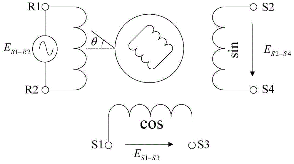
[0053] Schematic diagram of the rotary transformer figure 1 As shown, the primary field winding (R1-R2) and the two-phase secondary induction windings (S1-S3 and S2-S4) are on the stator side of the motor. When working, a 20KHz sinusoidal excitation signal is applied to the primary excitation winding R1-R2, and the output voltage of the secondary induction winding changes with the angle between the rotor and the primary excitation winding. The relationship between them is as follows:
[0054] E. R1-R2 =E 0sin(ωt)(1)
[0055] E. S1-S3 =KE 0 sin(ωt)sinθ(2)
[0056] E. S2-S4 =KE 0 sin(ωt)cosθ(3)
[0057] In the formula, E 0 is the voltage amplitude of the sinusoidal excitation signal, ω is the angular frequency of the sinusoidal excitation signal, K is the transformation ratio of the resolver, and θ is the angle between the primary excitation ...
PUM
 Abstract
Description
Claims
Application Information