
A low-speed wind tunnel model position and attitude ultrasonic measurement system

A technology of ultrasonic measurement and model, applied in the field of wind tunnel test, can solve the problem of low accuracy of ultrasonic ranging, achieve the effect of avoiding Doppler effect and improving accuracy

Active Publication Date: 2017-07-07
LOW SPEED AERODYNAMIC INST OF CHINESE AERODYNAMIC RES & DEV CENT
View PDF9 Cites 0 Cited by
  • Summary
  • Abstract
  • Description
  • Claims
  • Application Information

AI Technical Summary

Problems solved by technology

However, judging from the current application situation, since the speed of sound is treated as a constant in ultrasonic ranging, and due to the influence of the Doppler effect, the accuracy of ultrasonic ranging is not high

Method used


Image

  • A low-speed wind tunnel model position and attitude ultrasonic measurement system
  • A low-speed wind tunnel model position and attitude ultrasonic measurement system
  • A low-speed wind tunnel model position and attitude ultrasonic measurement system

Examples


Embodiment Construction

[0024] The present invention is implemented through the following steps:

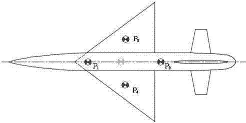
[0025] One is to fix the target ultrasonic sensor (receiving and sending integrated ultrasonic sensor) on the test model. In order to prevent the model from being deformed by wind load to affect the measurement accuracy, the target ultrasonic sensor should be installed in a position with small deformation. Secondly, in order to improve the measurement accuracy, the target ultrasonic sensor should be as far away as possible from the coordinate origin of the model coordinate axis system. In addition, in order to avoid the axis conversion error between the wind tunnel coordinate axis system and the model coordinate axis system, the distance between the target points should not be too large, and the number of target points should be no less than 4. Such as figure 1 As shown. In the ultrasonic measurement process, the target ultrasonic sensor installed on the model and the beacon sensor installed around the ...


PUM


Abstract

The invention discloses a low-speed wind tunnel model position and posture ultrasonic measurement system, which includes a controller, a precision stabilized power supply, and a target ultrasonic sensor, a beacon ultrasonic sensor and a real-time sound velocity measurement sensor respectively connected to the controller through cables; and The method of calibrating and demarcating the beacon ultrasonic sensor and the real-time sound velocity measurement ultrasonic sensor by using the base point calibration method and the real-time sound velocity measurement ultrasonic sensor by using the coordinate coincidence method; using the beacon ultrasonic sensor to obtain the upper 3 The coordinates of one or more target ultrasonic sensors on the wind tunnel coordinate axis and the coordinates of these sensors on the model coordinate axis can finally obtain the complete low-speed wind tunnel test model at this moment by solving the transformation parameters of the two coordinate axes. Pose parameters; the present invention adopts ultrasonic measurement of model poses, which can realize non-contact measurement of low-speed wind tunnel model poses, avoiding the interference effects of installation conditions and measuring equipment in the test section on the wind tunnel flow field, thereby avoiding the influence of Model the influence of aerodynamic data measurements.

Description

Technical field [0001] The invention relates to the field of wind tunnel tests, in particular to a low-speed wind tunnel model pose ultrasonic measuring system. Background technique [0002] The pose (position and attitude) of the test model is one of the key parameters required to be obtained during the low-speed wind tunnel test, and its accuracy is of great significance to the test. In the process of low-speed wind tunnel tests, currently commonly used model pose measurement methods include support mechanism nominal value substitution method, laser grating measurement method, gravity acceleration sensor measurement method, gyroscope measurement method, image measurement method, and photoelectric position sensitive detector measurement Due to the limitations of each method’s own characteristics, each method has more or less problems or defects. So far, no complete pose parameters have been found (position parameters in the three linear displacement directions). And three aviat...

Claims


Application Information

Patent Timeline
Patent Type & Authority Patents(China)
IPC IPC(8): G01M9/06
Inventor 张钧孙海生朱本华刘志涛梁勇祝明红聂博文温渝昌周述光张鹏李进学万琪明江鲲鹏
Owner LOW SPEED AERODYNAMIC INST OF CHINESE AERODYNAMIC RES & DEV CENT
Learn More