A Visualized Liquid-liquid Two-phase Flow Loop Experimental Device

An experimental device and loop technology, which is applied to measurement devices, fluid dynamics tests, instruments, etc., can solve the problems of large parameter variation range, huge differences in measured data, and inability to compare with each other, so as to reduce workload, large utilization rate, Full-featured effects

Inactive Publication Date: 2018-01-12
SOUTHWEST PETROLEUM UNIV
View PDF7 Cites 0 Cited by
  • Summary
  • Abstract
  • Description
  • Claims
  • Application Information

AI Technical Summary

Problems solved by technology

[0002] In today's industrial production, the development of nuclear energy, chemical industry, and petroleum industry has strongly promoted various researches in the field of multiphase flow, and there has been no substantial breakthrough in the research of liquid-liquid two-phase flow.
The parameters obtained by different materials, pipe diameters, and experimental methods vary widely, and the measured data vary widely, so they cannot be compared with each other.
However, the existing indoor experimental devices are all simple devices that simply realize two-phase contact flow, and cannot simulate the real state of the liquid-liquid two-phase in the pipeline during the actual production process.

Method used


Image

  • A Visualized Liquid-liquid Two-phase Flow Loop Experimental Device
  • A Visualized Liquid-liquid Two-phase Flow Loop Experimental Device
  • A Visualized Liquid-liquid Two-phase Flow Loop Experimental Device

Examples


Embodiment Construction

[0019] The present invention will be described in detail below in conjunction with the accompanying drawings and implementation examples.

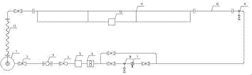
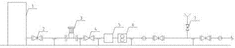
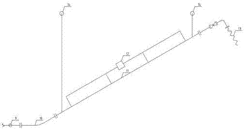
[0020] see figure 1 , the loop experiment device consists of a liquid storage tank 1, an outlet valve 2, a centrifugal pump 3, a flow regulating valve 4, a temperature transmitter 5, a flow transmitter 6, a filling system 7, a first blowdown valve 8, and a second blowdown valve The valve 9, the acrylic elbow 10, the upwardly inclined pipeline 11, the differential pressure transmitter 12, and the return system 13 are sequentially connected by flanges. The pipe diameter of the loop test device is 50mm, and the materials are galvanized steel pipe, acrylic pipe and steel wire spiral hose. The design dimensions and functions of each part of the device are as follows:

[0021] The size of the liquid storage tank 1 is a cylindrical steel barrel with a diameter of 323.9mm and a height of 1200mm. The bottom of the liquid storage tank is an inver...


PUM


Abstract

The invention discloses a visualized liquid-liquid diphasic loop experiment device, which is characterized by comprising a liquid storage tank, an outlet valve, a centrifugal pump, a temperature transmitter, a pressure transmitter, a charging system, an acrylic observation pipe segment, an upper inclination pipeline, a backflow system and data acquisition system which constitute a closed experiment loop. The experiment system is designed according to shear stress similar principle and accords with the hydrodynamics dynamic characteristics. The charging system can realize a liquid-liquid original state of any water content; the observation and recording of the flowing characteristics of the oil-water diphasic flow at the horizontal segment, the bended pipe and the upper-layer pipe segment are performed through an acrylic pipe; and the collection and the later period analysis of the related parameters of the experiment process are performed through a data collection system consisting of the temperature transmitter, the pressure transmitter and a pressure difference transmitter at the upper-layer pipe segment. The invention is used for the solar power generating system.

Description

technical field [0001] The invention is an experimental device based on a loop test frame, which can visually observe the experimental phenomenon and flow pattern of liquid-liquid two-phase flow, and collect and analyze parameters such as temperature, flow rate and pressure drop during the test process. Background technique [0002] In today's industrial production, the development of nuclear energy, chemical industry, and petroleum industry has strongly promoted various researches in the field of multiphase flow, and there has been no substantial breakthrough in the research of liquid-liquid two-phase flow. In the actual production of the petroleum industry, processes such as crude oil production with water and oil top water production of refined oil are typical liquid-liquid two-phase flow. Studying the flow law and mechanism of two-phase flow can reduce energy consumption in the production process, reduce internal corrosion of pipelines and promote multi-phase mixed trans...

Claims


Application Information

Patent Timeline
Patent Type & Authority Patents(China)
IPC IPC(8): G01M10/00
Inventor 宋晓琴熊柯杰张涛余东亮陈妍君杨月新黄诗嵬骆宋洋李佳佳
Owner SOUTHWEST PETROLEUM UNIV
Why Eureka
Try Eureka