Dewatering device for medical treatment

A dehydration device, horizontally placed technology, applied in the field of medical equipment, can solve the problems of inconvenient use, high cost, large volume, etc., and achieve the effect of fast dehydration, convenient use and obvious effect

Active Publication Date: 2016-01-06
HAIMEN THE YUECAI TEXTILE TECH CO LTD
View PDF5 Cites 8 Cited by
  • Summary
  • Abstract
  • Description
  • Claims
  • Application Information

AI Technical Summary

Problems solved by technology

[0002] In pathological diagnosis, a dehydrator is often used to dehydrate pathological slices. However, there is no fixed place for pl

Method used


Image

  • Dewatering device for medical treatment

Examples


Embodiment Construction

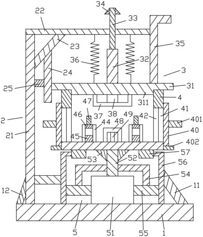
[0019] Such as figure 1 As shown, the medical dehydration device of the present invention includes a base plate 1, a bracket device 2 located above the base plate 1, a cover device 3 located above the base plate 1, and a frame body 4 located below the cover device 3 And the motor device 5 located under the frame body 4 .

[0020] Such as figure 1 As shown, the base plate 1 is a cuboid, the base plate 1 is placed horizontally, and the base plate 1 is located at the lowermost end. Two oblique rods 12. The first slanting rod 11 is inclined. The first slanting rod 11 is located on the right side and above the bottom plate 1 . The lower end of the first slanting rod 11 is fixedly connected to the upper surface of the bottom plate 1 . The second slanting rod 12 is inclined. The second slanting rod 12 is located above and to the left of the bottom plate 1 . The lower end of the second slanting rod 12 is fixedly connected to the upper surface of the bottom plate 1 .

[0021] Such ...


PUM


Abstract

A dewatering device for medical treatment comprises a bottom plate, a support device, a cover plate device, a frame body and a motor device. A first inclined rod and a second inclined rod are arranged on the bottom plate. A first supporting rod, a first transverse rod, a third inclined rod, a first vertical rod and a second transverse rod are arranged on the support device. A first cover plate, a second vertical rod, a third vertical rod, a positioning ring, a pull frame, a first spring, a first cooling frame and a first heating bar are arranged on the cover plate device. The frame body is provided with a first through hole, a first filter screen, a blocking column, a cushion block, a second cover plate, a first holding rod, a second cooling frame, a second heating bar and a check ring. The motor device is provided with a motor, a rotating shaft, a fixed ring, a positioning frame, a third transverse rod, a fixed frame and a wheel. Sufficient dewatering and drying can be conducted on medical instruments, dewatering is rapid, the effect is obvious, medical work efficiency can be greatly improved, labor intensity of medical staff is relieved, medical instruments are disinfected after heating, and disease infection is avoided.

Description

technical field [0001] The invention relates to the technical field of medical devices, in particular to a medical dehydration device. Background technique [0002] In pathological diagnosis, a dehydrator is often used to dehydrate pathological slices. However, there is no fixed place for placing slices in the inner tank of the existing dehydrator, which is inconvenient to use, and the volume is large and the cost is high. [0003] Therefore, it is necessary to provide a new technical solution to solve the above technical problems. Contents of the invention [0004] The object of the present invention is to provide a dehydration device for medical treatment which can effectively solve the above technical problems. [0005] In order to solve the above technical problems, the present invention adopts the following technical solutions: [0006] A dehydration device for medical treatment, the dehydration device for medical treatment comprises a base plate, a bracket device l...

Claims


Application Information

Patent Timeline
IPC IPC(8): G01N1/44G01N1/40
Inventor 黄斌
Owner HAIMEN THE YUECAI TEXTILE TECH CO LTD
Why Eureka
Try Eureka