Transformer for welding machine

A transformer and welding machine technology, which is applied in the direction of transformer/inductor cooling, transformer/inductor magnetic core, transformer/inductor parts, etc., can solve the problems of iron core quality degradation, accelerated transformer aging, and increased magnetic induction intensity. Achieve the effect of convenient operation, convenient disassembly and good heat dissipation effect

Inactive Publication Date: 2016-01-06
SICHUAN MORROW WELDING DEV
View PDF6 Cites 1 Cited by
  • Summary
  • Abstract
  • Description
  • Claims
  • Application Information

AI Technical Summary

Problems solved by technology

[0002] After the welding machine transformer is repaired, the no-load current will generally increase, especially the high-voltage range. The reason for the above problems is that the quality of the iron core decreases after the repair. At the end, there will always be some pieces that cannot be inserted, so the cross-sectional area of ​​the iron core is reduced and the magnetic induction intensity is increased; on the other hand, the reason is that the yoke iron silicon steel sheet is curled or piled up, causing the core air gap to become larger
In addition, in actual use, the transformer is prone to failure and needs to be disassembled frequently. However, the iron core of the existing transformer is troublesome to disassemble. If the temperature exceeds the temperature limit of the insulating material, it is easy to damage the transformer and accelerate the aging of the transformer

Method used


Image

  • Transformer for welding machine

Examples


Embodiment 1

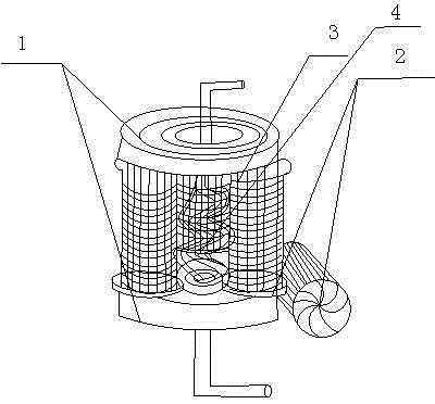
[0015] like figure 1 As shown, the present invention includes a yoke 1, a plurality of stems 2, a coil 3 and a water circulation pipe 4. The yoke 1 is rolled from a strip-shaped cold-rolled silicon steel sheet, and a plurality of stems are located between two yokes 1. Between two yoke irons 1 and multiple core columns are fixed by bolts; the water circulation pipe 4 penetrates from the center of one yoke iron and spirally extends downward through the cavity surrounded by multiple core columns 2 , passing through the middle of another yoke.

[0016] The transformer is sleeved on the core column through a coil, and the yoke is connected to three iron core columns to close the magnetic circuit, and the yoke is rolled from a strip-shaped cold-rolled silicon steel sheet. Bolts are fixed. When the transformer needs to be disassembled, only need to remove the corresponding bolts to realize the disassembly of the iron core column and the yoke iron, then replace the faulty core colum...

Embodiment 2

[0018] This embodiment is preferably as follows on the basis of Embodiment 1: the water circulation pipeline 4 includes a helically coiled main pipe and a plurality of helically coiled branch pipes connected to the main pipe. The design of more branch pipes can allow more water to stay in the cavity formed by multiple stems and take away more heat.

[0019] Each iron core column 2 is formed by lamination of silicon steel sheet inserts with an involute cross-section. This arrangement can avoid curling of the core post during the connection and fixation process with the yoke iron.

[0020] There are three stem pillars 2, and the three stem pillars are triangularly distributed. Improve the stability of the transformer.


PUM


Abstract

The invention discloses a transformer for a welding machine. The transformer comprises yokes, multiple core columns, coils and a water circulating pipeline. The yokes are formed by rolling strip-shaped cold-rolling silicon steel sheets. The multiple core columns are located between the two yokes. The two yokes and the core columns are fixed through bolts. The water circulating pipeline penetrates from the center of one yoke, is spirally wound, extends downwards to penetrate through a cavity enclosed by the multiple core columns, and penetrates out of the middle of the other yoke. By means of the principle, the transformer is convenient to disassemble, even if iron cores are disassembled many times, the quality is not prone to being reduced, edge curling or piling of the yokes is avoided, heat dissipation is ensured, and the situation that because temperature rises too fast, the transformer ages fast is avoided.

Description

technical field [0001] The invention relates to the field of welding machines, in particular to a transformer for welding machines. Background technique [0002] After the welding machine transformer is repaired, the no-load current will generally increase, especially the high-voltage range. The reason for the above problems is that the quality of the iron core decreases after the repair. At the end, there will always be some pieces that cannot be inserted, so the cross-sectional area of ​​the iron core is reduced and the magnetic induction intensity is increased; on the other hand, the reason is that the yoke iron silicon steel sheet is curled or Pile up, causing the core air gap to become larger. In addition, in actual use, the transformer is prone to failure and needs to be disassembled frequently. However, the iron core of the existing transformer is troublesome to disassemble. If the temperature exceeds the temperature limit of the insulating material, it is easy to d...

Claims


Application Information

Patent Timeline
Patent Type & Authority Applications(China)
IPC IPC(8): H01F27/26H01F27/245H01F27/16
Inventor 杨友涛
Owner SICHUAN MORROW WELDING DEV
Why Eureka
Try Eureka