Power generator and wind generating set
A technology for wind power generators and generators, applied in the direction of magnetic circuit shape/style/structure, magnetic circuit static parts, magnetic circuit rotating parts, etc., can solve problems such as poor generator performance and uneven air gap, and achieve Effect of improving electrical and mechanical properties
- Summary
- Abstract
- Description
- Claims
- Application Information
AI Technical Summary
Problems solved by technology
Method used
Image
Examples
Embodiment 1
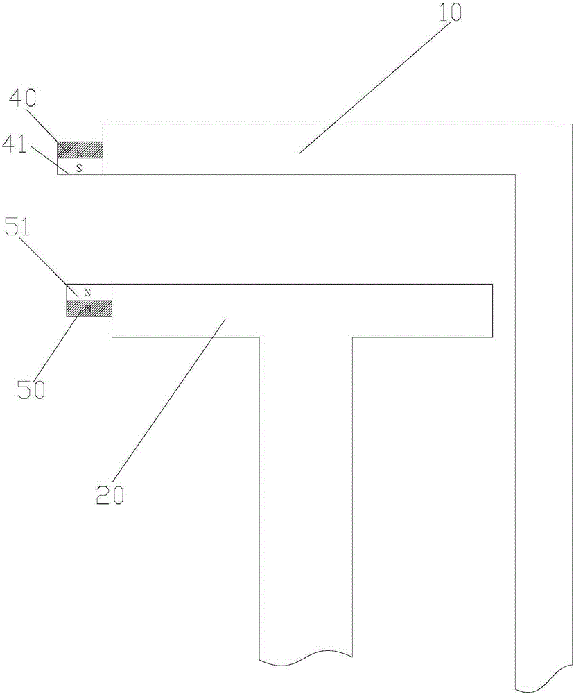
[0030] It should be noted that the generator in this embodiment can be an external rotor generator, that is, the rotor 10 is sleeved outside the stator 20 ;
[0031] Such as image 3 As shown, the generator includes a rotor 10, a stator 20, and an air gap 30 formed between the rotor 10 and the stator 20 along the radial direction of the generator. In this embodiment, the generator further includes a first air gap control assembly 40 and a second air gap control assembly 50 . The first air gap control assembly 40 is disposed on the rotor 10 (when the rotor 10 moves radially, the first air gap control assembly 40 moves accordingly), and the first air gap control assembly 40 has a first magnetic pole 41 . The second air gap control assembly 50 is arranged on the stator 20 (when the stator 20 moves radially, the second air gap control assembly 50 moves accordingly), and the second air gap control assembly 50 has a second magnetic pole 51, the first The magnetic pole 41 and the s...
Embodiment 2
[0043] Such as Figure 5 As shown, in this embodiment, except for the setting positions of the first air gap control assembly 40 and the second air gap control assembly 50 and the connection with the corresponding rotor 10 and stator 20, the others are the same as those in the embodiment one by one. Sincerely, I will not repeat them here.
[0044] Specifically, the end surface of the rotor 10 is provided with a rotor end cover plate 11 extending in the radial direction to increase the rigidity of the rotor 10. Correspondingly, an additional connecting piece 21 is fixedly arranged on the stator 20, and the additional connecting piece 21 is L-shaped. , which has a vertical section extending in the radial direction of the generator, the rotor end cover plate 11 corresponds to the vertical section in the radial direction, and there is a gap between them. The first permanent magnet of the first air gap control assembly 40 is arranged on the end surface of the rotor end cover plate...
Embodiment 3
[0047] Such as Figure 6 As shown, in this embodiment, except that the first air gap control assembly 40 and / or the second air gap control assembly 50 include electromagnets, other structures, setting positions and principles are the same as those of the second embodiment, and will not be repeated here. repeat.
[0048] Specifically, in this embodiment, the permanent magnets are arranged on the rotor end cover plate 11 , and the electromagnets are arranged on the vertical section of the additional connecting piece 21 . Of course, the permanent magnets can be directly arranged on the end surface of the rotor 10 , and the electromagnets can be directly arranged on the end surface of the stator 20 . In other embodiments, electromagnets may also be provided on both the rotor end cover plate 11 and the vertical section.
[0049] Preferably, since the magnetic force of the electromagnet can be changed by changing the magnitude of the current, it has better controllability. In orde...
PUM
 Abstract
Description
Claims
Application Information
 - R&D
- Intellectual Property
- Life Sciences
- Materials
- Tech Scout
- Unparalleled Data Quality
- Higher Quality Content
- 60% Fewer Hallucinations
Browse by: Latest US Patents, China's latest patents, Technical Efficacy Thesaurus, Application Domain, Technology Topic, Popular Technical Reports.
© 2025 PatSnap. All rights reserved.Legal|Privacy policy|Modern Slavery Act Transparency Statement|Sitemap|About US| Contact US: help@patsnap.com


