Variable-modal cascade converter

A technology of cascaded converters and converters, which is applied in the DC/DC converter and AC/DC fields, can solve problems such as unproposed solutions and low converter efficiency, and achieve the effect of simple and ingenious and high efficiency

Inactive Publication Date: 2016-01-06
ZHEJIANG UNIV +1
View PDF0 Cites 13 Cited by
  • Summary
  • Abstract
  • Description
  • Claims
  • Application Information

AI Technical Summary

Problems solved by technology

[0005] The front and rear two-stage converters are cascaded together, and the efficiency of the converter i

Method used


Image

  • Variable-modal cascade converter
  • Variable-modal cascade converter
  • Variable-modal cascade converter

Examples


Embodiment Construction

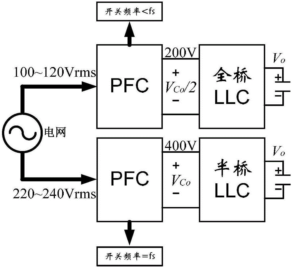
[0038] figure 1 It is a functional block diagram of the variable-mode cascaded converter composed of a PFC converter and a full-bridge converter proposed by the present invention. Such as figure 1 As shown, the variable-mode cascade converter of the present invention is formed by connecting the output of the PFC converter with the input of the full-bridge converter, including a front-stage PFC converter and a rear-stage full-bridge converter. A capacitive coupling is used between the front and rear circuits to facilitate the independent control of the front and rear circuits. The input of the PFC converter and the output of the full-bridge converter are the input and output of the variable-mode cascade converter, respectively.

[0039] From figure 1 The general structural block diagram of the variable mode cascaded converter shown shows that the circuit work includes the following steps:

[0040] (1) Measure the input voltage of the pre-stage PFC converter, that is figure ...


PUM


Abstract

The invention discloses a variable-modal cascade converter. Output of a PFC converter is connected with input of a full-bridge converter to form the variable-modal cascade converter; the input of the PFC converter and the output of the full-bridge converter are input and output of the variable-modal cascade converter respectively; output voltage of the PFC converter controls a target value; the output voltage is determined according to the input voltage size; and the full-bridge converter selectively works in a half-bridge mode or a full-bridge mode according to the output voltage. According to the variable-modal cascade converter, the problem of low circuit efficiency when input voltage is low in related technologies is solved; high efficiency within a full range is achieved; and the overall performance of a circuit is improved.

Description

technical field [0001] The present invention relates to an AC / DC, DC / DC converter, in particular to a variable-mode cascaded converter, which realizes cascaded power factor correction (PowerFactorCorrection, PFC for short) and DC / DC conversion. Background technique [0002] Power electronic converters have been widely used in all aspects of human production and life. The efficiency of converters is directly related to energy efficiency, work reliability, small size and light weight, and material saving; Very serious harmonic pollution. [0003] Therefore, many universal AC / DC converters around the world have adopted the PFC structure as the front-end access circuit. It is a topology with relatively high efficiency and low input current harmonics. When the input voltage is low, due to the corresponding large input current, there will be large conduction loss and switching loss in the converter, so the bottleneck for further efficiency improvement lies in the low input voltag...

Claims


Application Information

Patent Timeline
IPC IPC(8): H02M1/42H02M7/219
CPCY02B70/10Y02P80/10
Inventor 黄龙吕征宇姚文熙叶志红
Owner ZHEJIANG UNIV
Why Eureka
Try Eureka