Pulling expansion type solar device with revolution function

A pull-and-deploy, solar energy device technology, applied in the field of solar power generation, can solve the problems of inflexible rotation of the solar device, affecting the solar energy absorption efficiency, single structure of the solar cell panel, etc.

Inactive Publication Date: 2016-01-06
HEILONGJIANG XINGAN NEW ENERGY
View PDF6 Cites 3 Cited by
  • Summary
  • Abstract
  • Description
  • Claims
  • Application Information

AI Technical Summary

Problems solved by technology

[0005] The purpose of the present invention is to solve the problems of inflexible rotation of existing solar devices and the single structure of solar panels, which affect the efficiency of solar energy absorption, and provide a pull-out solar device with a rotary function

Method used


Image

  • Pulling expansion type solar device with revolution function
  • Pulling expansion type solar device with revolution function
  • Pulling expansion type solar device with revolution function

Examples


specific Embodiment approach 1

[0019] Specific implementation mode one: combine figure 1 , figure 2 , Figure 4 and Figure 5 Describe this embodiment. A pull-out solar device with a rotary function described in this embodiment includes a pull-out mechanism and a rotation mechanism; the pull-out mechanism includes a plurality of sequentially stacked solar panels 1-1, and a plurality of solar panels 1-1 can be unfolded into a ladder shape in turn; the turning mechanism includes a rotatable upper base 2-3; the pull-out mechanism is arranged on the upper surface of the upper base 2-3.

[0020] When the solar device described in this embodiment is in use, the solar cell panels 1-1 are pulled and unfolded in steps in sequence, as shown in figure 2 and Figure 4 As shown, the upper base 2-3 is flat, the solar cell panel 1-1 is arranged on the upper base 2-3, and the upper base 2-3 can rotate in a plane around its central axis, as Figure 5 As shown, the solar cell panel 1-1 is fixed on the upper base 2-3 th...

specific Embodiment approach 2

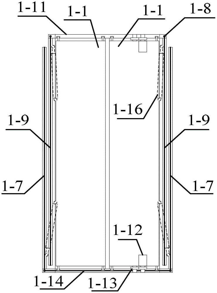
[0021] Specific implementation mode 2: Combining Figure 1 to Figure 4 Describe this embodiment. This embodiment is a further limitation of the drawable and deployable solar device with a rotary function described in Embodiment 1. In this embodiment, the drawable and deployable mechanism also includes trusses 1-11 , the truss 1-11 is a structure with openings on both sides, the truss 1-11 is fixed on the upper base 2-3, the number of solar panels 1-1 is an even number, and two solar panels 1-1 are fixed side by side on the truss Inside 1-11, other solar battery panels 1-1 are evenly distributed on both sides of the two solar battery panels 1-1, starting from the two solar battery panels 1-1, the solar battery panels 1 on both sides -1 are connected sequentially along the slide rail on the lower surface of the adjacent previous solar cell panel 1-1 to form a ladder arrangement.

[0022] figure 1 and image 3 Shown is the state when the solar cell panels 1-1 are put away, wh...

specific Embodiment approach 3

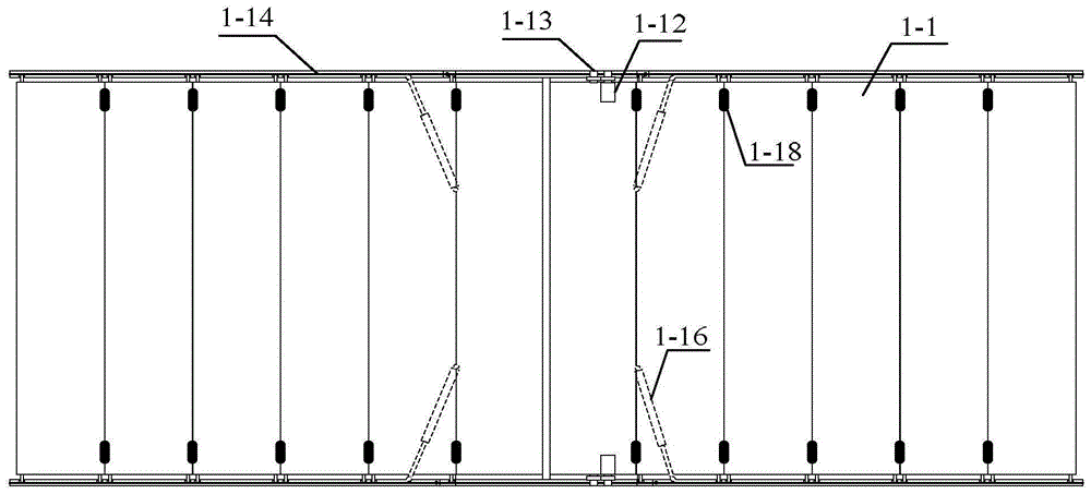
[0023] Specific implementation mode three: combination figure 1 This embodiment is described. This embodiment is a further limitation of the pull-out solar device with a rotary function described in Embodiments 1 and 2. In this embodiment, the first part of each solar cell panel 1-1 Limiting mechanism 1-18 is all provided with end and end.

[0024] When the solar battery panels 1-1 are in the retracted state, it is only necessary to pull the bottom two solar battery panels 1-1 to both sides. figure 1 All the solar panels 1-1 have the same size, when the bottom two solar panels 1-1 travel the width of one solar panel 1-1, the limit mechanism 1-1 at the end of the solar panel 1-1 18 is combined with the limit mechanism 1-18 at the head end of the next solar battery panel 1-1, thereby pulling the next solar battery panel 1-1 to be pulled outward, and so on, all solar battery panels 1-1 will be sequentially Unfold without pulling each solar panel 1-1 individually.


PUM


Abstract

The invention relates to the pulling expansion type solar device with a revolution function, relating to the power generation technology of the mobile type solar energy emergency security power station. The pulling expansion type solar device with the revolution function solves the problems that the prior art is not flexible in rotation, and the structure of the solar battery panel is single, which affect the absorption efficiency of the solar energy. The pulling expansion type solar device with a revolution function comprises a plurality of solar energy battery panels which are successively stacked; the plurality of the solar energy battery panels can be successively expanded into a staircase shape; a decelerator motor is used for driving two reverse wheels to rotate along the opposite directions so as to drive two solar battery panels to expand and fold; in a revolution mechanism, the upper surface of a lower base and the lower surface of an upper base are provided with annular grooves; and rolling steel balls are arranged between the annular groove of the lower base and the annular groove of the upper base. The solar battery panel can be rotated flexibly and improves the usage efficiency of the solar energy.

Description

technical field [0001] The invention relates to the solar power generation technology of a mobile solar emergency protection power station. Background technique [0002] Solar energy is the energy produced by the fusion of internal hydrogen atoms to release huge nuclear energy, which is the radiant energy from the sun. Most of the energy required by human beings comes directly or indirectly from the sun. Plants release oxygen and absorb carbon dioxide through photosynthesis, and convert solar energy into chemical energy and store it in plants. Fossil fuels such as coal, oil, and natural gas are also formed by the evolution of animals and plants buried in the ground in ancient times through long geological ages. In addition, water energy, wind energy, etc. are also converted from solar energy. The energy contained in the earth itself usually refers to the energy related to the heat energy inside the earth and the energy related to the nuclear reaction. Solar power generat...

Claims


Application Information

Patent Timeline
Patent Type & Authority Applications(China)
IPC IPC(8): H02S20/32H02S30/20
CPCY02E10/50
Inventor 于丰泽陈怀春于占江
Owner HEILONGJIANG XINGAN NEW ENERGY
Why Eureka
Try Eureka