Method for preventing milling leakage of milling groove of circuit board
A technology for circuit boards and troughs, which is applied in chemical/electrolytic methods to remove conductive materials, printed circuits, and printed circuit manufacturing. Effect, eliminate leakage, reduce the effect of defective and defective products
- Summary
- Abstract
- Description
- Claims
- Application Information
AI Technical Summary
Problems solved by technology
Method used
Image

Examples
Embodiment 1
[0019] Embodiment 1 A kind of method of eliminating leakage of circuit board grooves with a groove width of more than 0.8mm
[0020] A method for preventing leakage of circuit board slots, comprising the steps of:
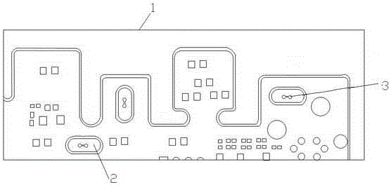
[0021] S1. Fabrication, pressing, and drilling of the inner circuit board, and electroplating the entire surface of the outer circuit board to form the outer circuit board 1 .
[0022] S2. Perform pattern transfer, exposure, display, and etching.
[0023] According to the distribution of the grooves 2 of the outer circuit board, make a film negative for graphic transfer. Use a film negative of the same size as the outer circuit board for production. When making film negatives, the gong groove area is the opaque part, and the two fool-proof PAD3s in the gong groove area and the lines connecting the two fool-proof PADs are the light-transmitting parts. Paste a layer of dry film on the surface of the outer circuit board, and then paste a film picture for exposure, ...
Embodiment 2
[0031] Embodiment 2 A method for preventing circuit board groove leakage with a groove width less than 0.8 mm
[0032] A method for preventing leakage of circuit board slots, comprising the steps of:
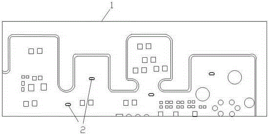
[0033] S1. Fabrication, pressing, and drilling of the inner circuit board, and electroplating the entire surface of the outer circuit board to form the outer circuit board 1 .
[0034] S2. Perform pattern transfer, exposure, display, and etching.
[0035] According to the distribution of the grooves 2 of the outer circuit board, make a film negative for graphic transfer. Use a film negative of the same size as the outer circuit board for production. When making film negatives, the gong groove area is an opaque part. Paste a layer of dry film on the surface of the outer circuit board, and then paste a film picture for exposure, development, etching, and removal of the dry film on the surface of the circuit board, so that the groove area of the etched circuit board surface is...
PUM
| Property | Measurement | Unit |
|---|---|---|
| Diameter | aaaaa | aaaaa |
Abstract
Description
Claims
Application Information