
Eureka
For R&D, Eureka makes reading and utilizing patents & technical documents easy.
Eureka AIR
Designed for self-driven R&D workflows. Generate viable solutions, solve complex R&D challenges, empower your innovation with AI.

Eureka Materials
Designed for material experts only. Revolutionize your material R&D, from search, analyze, to developing new materials.

TechResearch
Generate reliable direction feasibility study reports for your R&D in just a few steps.

TechSeek
Discover and master advanced knowledge NOW. Basics, ideas, possibilities, all at once.

TechMind
As an expert in R&D Theories, TechMind can generates customized viable solutions instantly.

TechRisk
Analyze your overall solution with one click, know your potential R&D risks in advance.

TechMonitor
Get weekly tech updates, stay abreast of the latest tech innovations and key insights.
Catheter system
A catheter and inner catheter technology, applied in the field of catheter systems, can solve problems such as blocking blood flow
- Summary
- Abstract
- Description
- Claims
- Application Information
AI Technical Summary
Problems solved by technology
Method used
Image

Examples
Embodiment Construction
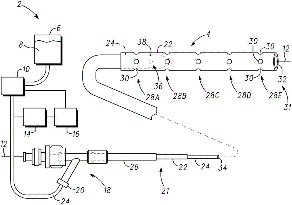
[0019] figure 1 A catheter system 2 according to one embodiment of the invention is shown. As will be described in detail herein, catheter system 2 is used to provide pressurized fluid (eg, thrombolytic drugs) at multiple sites for removal or destruction of thrombi from blood vessels, such as arteries or veins. By providing direct delivery of pressurized fluid along multiple sites, the pressurized fluid penetrates the clot more efficiently and reduces procedure time compared to other methods. In one example, thrombolytic drugs delivered to blood vessels include, but are not limited to, cytolytic drugs (e.g., tissue plasminogen activator (tPA)), or other agents that interact with and actively reduce thrombus size (e.g., , destroy, remove, minimize or eliminate) drugs. In some instances, after catheter system 2 delivers cytolytic or other drugs to actively reduce the size of the thrombus, a thrombectomy catheter is used to further macerate and aspirate any remaining thrombus ...
PUM
 Abstract
Description
Claims
Application Information
 - R&D Engineer
- R&D Manager
- IP Professional
- Industry Leading Data Capabilities
- Powerful AI technology
- Patent DNA Extraction
Browse by: Latest US Patents, China's latest patents, Technical Efficacy Thesaurus, Application Domain, Technology Topic, Popular Technical Reports.
© 2024 PatSnap. All rights reserved.Legal|Privacy policy|Modern Slavery Act Transparency Statement|Sitemap|About US| Contact US: help@patsnap.com