Photoirradiation device

A technology of light irradiation device and irradiation surface, which is applied in the directions of lighting device, light source, and elongated light source, etc., can solve the problems such as the overall enlargement of the light irradiation device.

Active Publication Date: 2016-01-06
HOYA CANDEO OPTRONICS
View PDF7 Cites 17 Cited by
  • Summary
  • Abstract
  • Description
  • Claims
  • Application Information

AI Technical Summary

Problems solved by technology

In order to solve the related problems, it is conceivable to arrange each LED unit away from the object to be irradiated, but such an arrangement will cause the problem of increasing the size of the entire light irradiation device.

Method used


Image

  • Photoirradiation device
  • Photoirradiation device
  • Photoirradiation device

Examples


Embodiment Construction

[0044]Hereinafter, embodiments of the present invention will be described in detail with reference to the accompanying drawings. Furthermore, the same or equivalent parts in the figures are marked with the same symbols, and the description is not repeated.

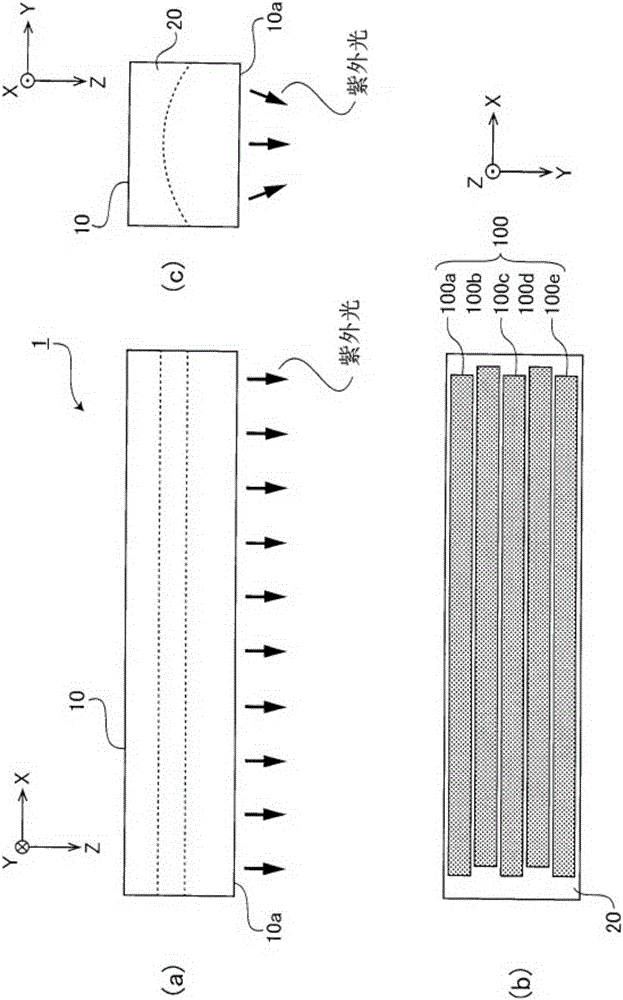
[0045] figure 1 It is an external view of the light irradiation apparatus 1 which concerns on the Example of this invention. The light irradiation device 1 of the present embodiment is a device mounted on a light source device that hardens an ultraviolet curable ink used as a cut sheet offset printing ink or an ultraviolet curable resin used as a sealant such as FPD (Flat Panel Display), and is described later. Said, it is arranged above the irradiation object, and emits linear ultraviolet light ( figure 2 (b)). In this specification, the long-side (line length) direction of the linear ultraviolet light emitted from the light irradiation device 1 is defined as the X-axis direction (first direction), and the short-side ...


PUM


Abstract

A photoirradiation device for irradiating a prescribed irradiation position on an irradiation surface with line-shaped light extending in a first direction and having a prescribed line width in a second direction perpendicular to the first direction is equipped with an optical unit for irradiating the irradiation surface with line-shaped light parallel to the first direction, and having: N number (N is an integer of 2 or higher) of light-source modules arranged in the first direction on a substrate with a first interval interposed therebetween, and positioned in a manner such that the optical axes thereof are oriented in a prescribed direction; and N number of optical elements for guiding the light from each of the light-source modules to a prescribed optical path, and positioned along the optical path of each of the light-source modules. Therein: each of the light-source modules has a light-emitting part extending in a first direction; and each of the optical elements magnifies the light emitted from the light-emitting parts at a prescribed magnification factor in the first direction, and satisfies conditional expression (1), given that the first interval is a, the length of the light-emitting parts in the first direction is b, and the prescribed magnification factor is alpha: alpha*b>=a ... (1).

Description

technical field [0001] The present invention relates to a light irradiation device for irradiating linear irradiation light, and in particular, to a light irradiation device including a plurality of light source modules arranged in a row on a substrate. Background technique [0002] Conventionally, UV-curable inks that are cured by irradiation with UV light have been used as inks for cut sheet offset printing. Moreover, an ultraviolet curable resin is used as a sealing agent of a liquid crystal panel, an organic EL (ElectroLuminescence) panel, etc., and FPD (FlatPanelDisplay). In general, for curing such UV-curable inks or UV-curable resins, an ultraviolet light irradiation device that irradiates ultraviolet light is used. However, especially in the use of sheet-fed offset printing and FPD, it is necessary to irradiate a wide range of radiation. Therefore, a linear light irradiation device that irradiates linear irradiation light is used. Such a linear light irradiation de...

Claims


Application Information

Patent Timeline
Patent Type & Authority Applications(China)
IPC IPC(8): F21K9/20F21Y103/10
CPCB41F23/0409B41F23/0406B41F23/045B41F23/0453
Inventor 岸根努
Owner HOYA CANDEO OPTRONICS
Why Eureka
Try Eureka