
Medical pressurizing device

A shell and push rod technology, applied in the field of medical equipment, can solve the problems that the user cannot intuitively understand the pressure value, the pressure value display is not accurate enough, the complex structure of the medical inflator, etc., and achieve a controllable and stable range of motion. The effect of exquisite structure design and few structural parts

Inactive Publication Date: 2016-01-13
江苏爱芮斯医疗科技有限责任公司
View PDF8 Cites 0 Cited by
  • Summary
  • Abstract
  • Description
  • Claims
  • Application Information

AI Technical Summary

Problems solved by technology

[0003] The existing medical pressurizer has a complex structure and is not easy to operate
Especially when rapid boosting is required, due to its own design flaws, it cannot be boosted to high pressure
And also can't release the pressure quickly
affect the efficacy of the treatment
Especially when performing vascular interventional treatment, there is a high requirement for the boosting speed. If the rapid boosting cannot be achieved, the treatment will be greatly affected.
At the same time, the complex structure of the medical charger not only increases the production cost but also increases the probability of product failure
[0004] At the same time, the existing pressure display device of the medical inflator cannot allow the user to understand the current pressure value more intuitively
And the display of the pressure value is not accurate enough

Method used


Image

  • Medical pressurizing device
  • Medical pressurizing device
  • Medical pressurizing device

Examples


Embodiment Construction

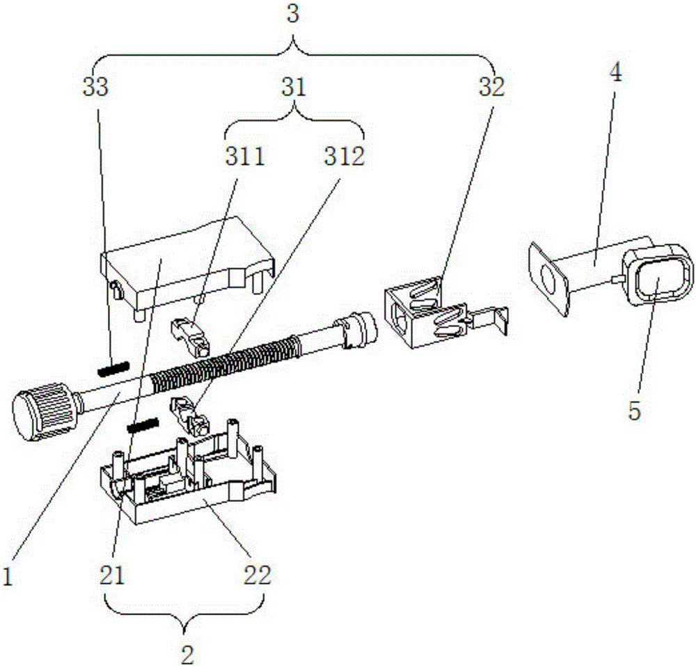
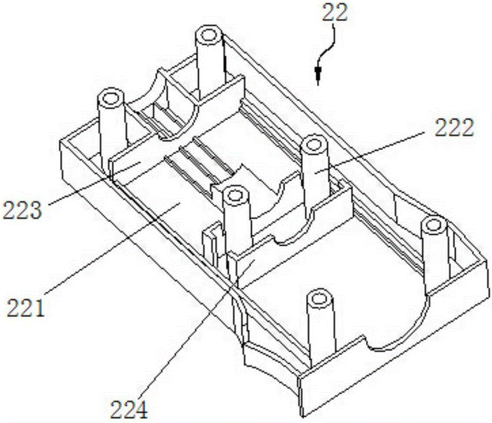
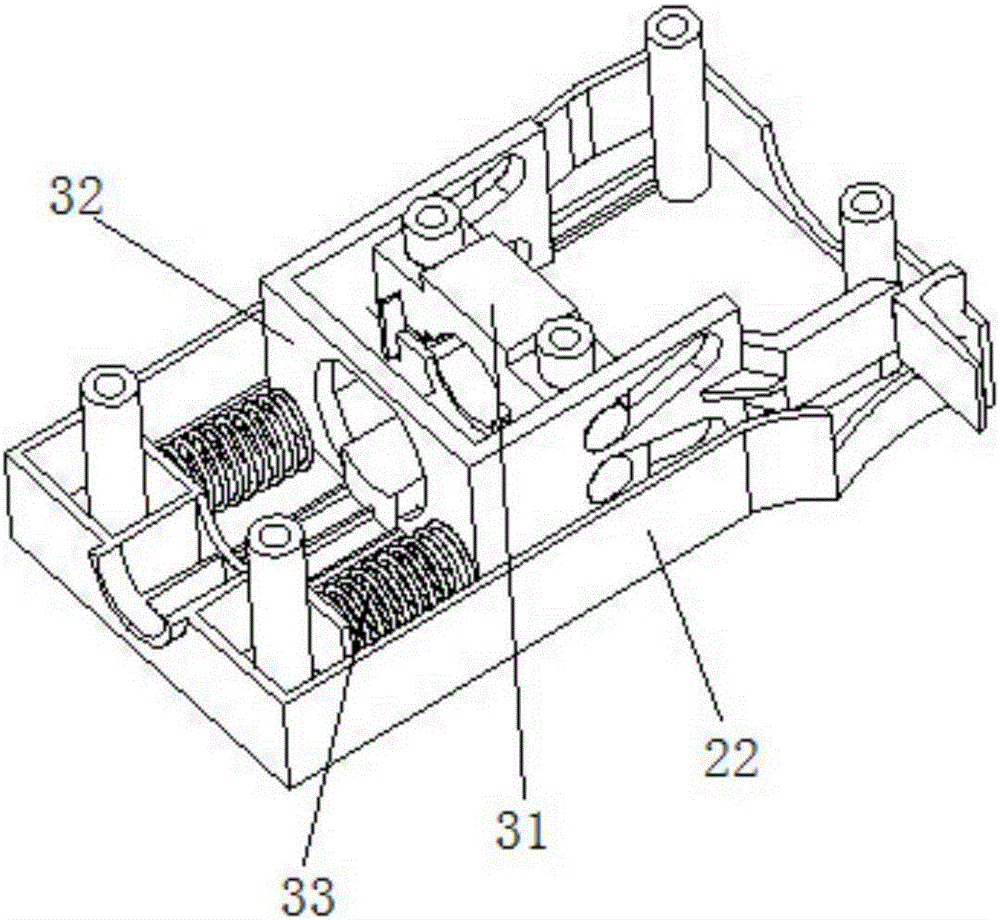
[0030] See Figure 1 to Figure 12 , the present invention has a piston device 1, a grip housing 2, a self-locking release device 3 and a bobbin 4; it is characterized in that: the piston device 1 includes a push rod 11 and a piston head 12; the self-locking release device 3 is set In the grip housing 2; the piston head 12 is connected to the front end of the push rod 11; the front end of the push rod 11 passes through the grip housing 2 and the self-locking release device 3 in the grip housing 2 and extends into the cylinder The inside of the tube 4; the piston head 12 is airtightly matched with the inner wall of the bobbin 4; the bobbin 4 is fixedly connected to the grip housing 2; the push rod 11 cooperates with the self-locking release device 3; the bobbin 4 is provided with a test connection end 41 communicating with its interior; the test connection end 41 is fixed with a pressure digital display device 5 .

[0031]The push rod 11 includes an integrally formed front conn...


PUM


Abstract

The invention relates to a medical pressurizing device. The medical pressurizing device comprises a piston device, a holding shell, a self-lock release device and a tube, wherein the piston device comprises a pushing rod and a piston head; the self-lock release device is arranged in the holding shell; the piston head is connected to the front end of the pushing rod; the front end of the pushing rod penetrates into the holding shell and the self-lock release device in the holding shell and stretches into the tube; the piston head is in tight fit with the inner wall of the tube; the tube is fixedly connected to the holding shell; the pushing rod is matched with the self-lock release device; a testing connecting end communicated with the inner side of the tube is arranged on the tube; a digital pressure display device is fixedly arranged on the testing connecting end. The medical pressurizing device has the beneficial effects that the design is smart, the structure is exquisite, the operation is convenient and rapid, the adjustment is visual, the control is precise, and the rapid decompression can be achieved.

Description

technical field [0001] The invention relates to the field of medical equipment, in particular to a medical pressure charger. Background technique [0002] In modern medicine, it is one of the more common treatment methods to expand human body parts or lumens with expansion instruments. During the expansion process, in order to ensure the safety of treatment, a device capable of pressurizing or depressurizing is often required. Therefore, there have been many medical pressurizers. [0003] The existing medical pressurizer has a complex structure and is not easy to operate. Especially when fast supercharging is required, due to its own design defects, it cannot be supercharged to high pressure. And also can't release the pressure quickly. Thereby affecting the treatment effect. Especially when performing vascular interventional treatment, there is a high requirement for the boosting speed. If the rapid boosting cannot be achieved, the treatment will be greatly affected. ...

Claims


Application Information

Patent Timeline
Patent Type & Authority Applications(China)
IPC IPC(8): A61M29/00F15B3/00
Inventor 张强
Owner 江苏爱芮斯医疗科技有限责任公司
Learn More