Flocculation concentration device with grille structure bodies and filtrate recycling tank with grille structure bodies

A technology of concentration device and structure, which is applied in the direction of filtration circuit, flocculation/sedimentation water/sewage treatment, filtration and separation, etc. It can solve the problems of low solid-liquid separation efficiency, slow propulsion speed, high water content, etc., and achieve growth flocculation reaction Time, increase the treatment capacity, reduce the effect of water content

Inactive Publication Date: 2016-01-13
AMCON FUJIAN ENVIRONMENT PROTECTION EQUIP CO LTD
View PDF5 Cites 1 Cited by
  • Summary
  • Abstract
  • Description
  • Claims
  • Application Information

AI Technical Summary

Problems solved by technology

The flocculation mixing tank only allows flocs to form, and then directly flows into the solid-liquid separation device without any concentration, so the efficiency of solid-liquid separation is low and the water content is high
[0003] In the prior art, the flocculation formed after stirring in the flocculation mixing tank usually flows directly into the solid-liquid separation device. During the self-flowing process, since the material has been continuously entering and the stirring has been continuously running, the flocculation time is also short. Therefore, it is inevitable that some materials that have not been flocculated will also be mixed into the body, resulting in the phenomenon of material running out of the solid-liquid separation device
The flocculation mixing tank mostly uses stirring to keep the flocs from settling, and then flows into the solid-liquid separation device through overflow. This solid-liquid separation is completely realized by the gravity of the material and the thrust of the stirring shaft itself. Due to the limited extrusion force , the moisture content cannot be lowered, and the agitator shaft itself is prone to slow propulsion speed or internal blockage of the solid-liquid separation device due to its weak thrust

Method used


Image

  • Flocculation concentration device with grille structure bodies and filtrate recycling tank with grille structure bodies
  • Flocculation concentration device with grille structure bodies and filtrate recycling tank with grille structure bodies
  • Flocculation concentration device with grille structure bodies and filtrate recycling tank with grille structure bodies

Examples


no. 1 example

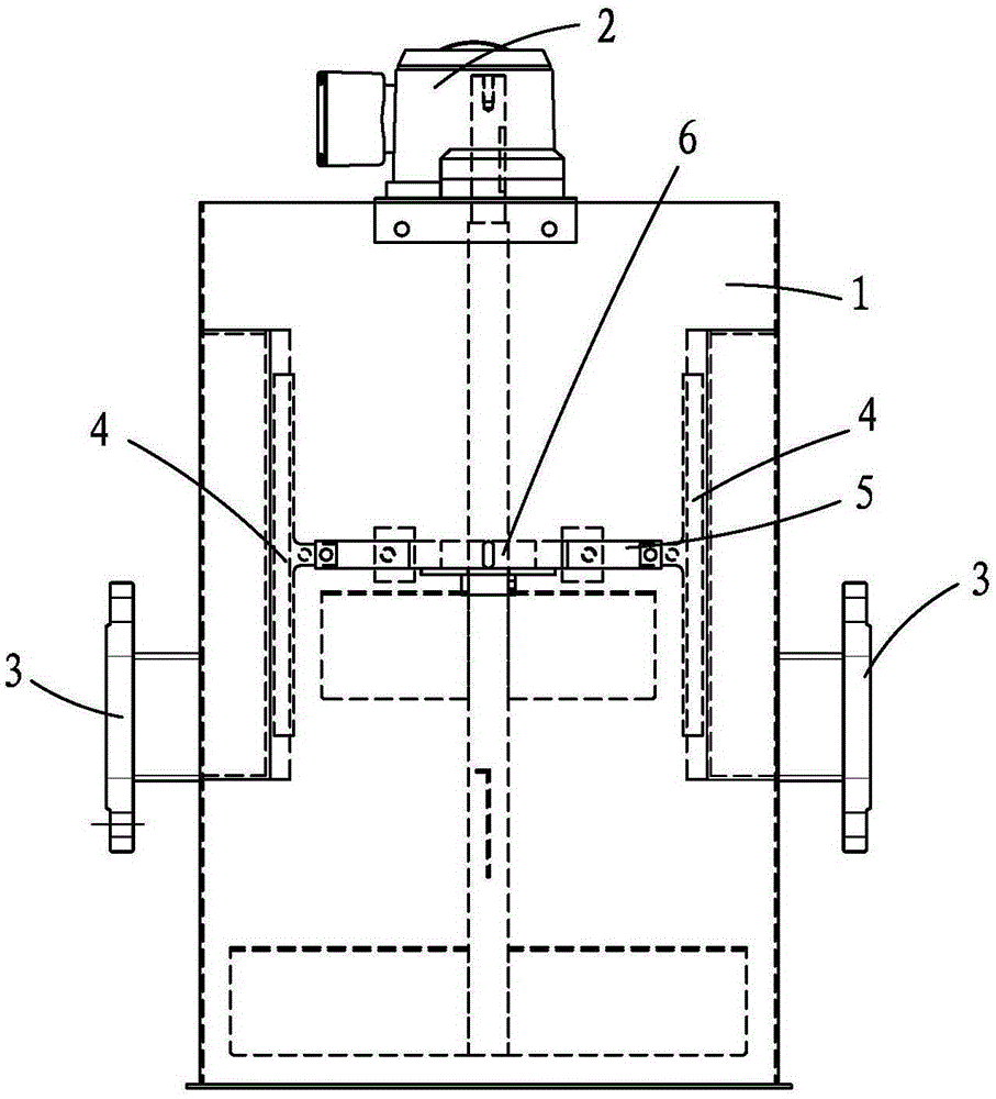
[0026] Such as figure 1 , 2 As shown in . and 3, a flocculation concentration device with a grid structure includes a flocculation mixing tank 1, a stirring device 2 is arranged in the flocculation mixing tank 1, and on two opposite tank walls of the flocculation mixing tank 1 A supernatant overflow port 3 is respectively provided, and a grid structure 4 is arranged at the supernatant liquid overflow port 3 .

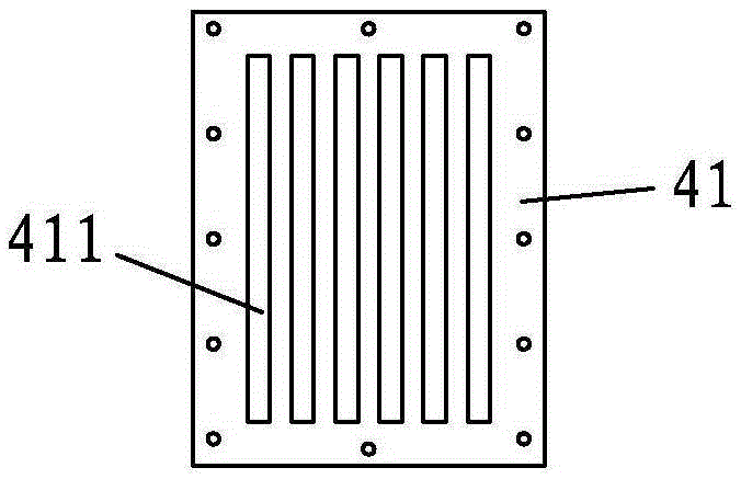
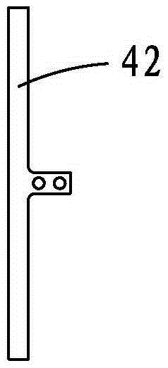
[0027] The grid structure 4 includes a fixed grid 41 and a plurality of grid bars 42, the fixed grid 41 is fixedly arranged at the supernatant overflow port 3 in the flocculation mixing tank 1, and the fixed grid The surface of the plate 41 is provided with a plurality of filter slits 411, and a grid bar 42 is arranged in each filter slit 411, and the grid bar 42 is connected to the stirring shaft of the stirring device 2 through a transmission rod 5 and an eccentric device 6. The eccentric device 6 on the stirring shaft drives the transmission rod 5 to make the grid ...

no. 2 example

[0030] Such as figure 2 , 3 , 4, a flocculation concentration device with a grid structure, including a flocculation mixing tank 1, a partition 7 is arranged in the flocculation mixing tank 1 to divide it into a flocculation reaction zone 11 and a concentration settlement zone 12; The height of the partition plate 7 is lower than the height of the flocculation mixing tank 1; the stirring device 2 is located in the flocculation reaction zone 11; the tank wall of the concentrated settlement zone 12 is provided with a supernatant overflow port 3 , a grid structure 4 is provided at the overflow port 3 of the supernatant liquid.

[0031] The grid structure 4 includes a fixed grid 41 and a plurality of grid bars 42, the fixed grid 41 is fixedly arranged at the supernatant overflow port 3 in the flocculation mixing tank 1, and the fixed grid The surface of the plate 41 is provided with a plurality of filter slits 411, and a grid bar 42 is arranged in each filter slit 411, and the ...

no. 3 example

[0037] Such as figure 2 , 3 , 5, a filtrate recovery tank 100 with a grid structure, the tank wall of the filtrate recovery tank 100 is provided with a grid structure 4.

[0038] The grid structure 4 includes a fixed grid 41 and a plurality of grid bars 42, the fixed grid 41 is fixedly arranged on the tank wall of the filtrate recovery tank 100, and the surface of the fixed grid 41 is provided with multiple Each filter slit 411 is provided with a grid bar 42 in each filter slot 411, and the grid bar 42 is driven by a driving device (not shown in the figure), thereby making the grid bar 42 move. The unblocked state of the filter slit 411 can be kept to avoid clogging.


PUM


Abstract

The invention discloses a flocculation concentration device with grille structure bodies and a filtrate recycling tank with the grille structure bodies. The flocculation concentration device comprises a flocculation mixing tank, a stirring device is arranged in the flocculation mixing tank, the tank wall of the flocculation mixing tank is provided with one or more than one supernatant overflow ports, and the grille structure bodies are arranged at the supernatant overflow ports; the tank wall of the filtrate recycling tank is provided with grille structure bodies; each grille structure body comprises multiple filtering seams which are formed side by side and multiple grille strips, one grille strip is arranged in each filtering seam, and relative motion is formed between the filtering seams and the grille strips. According to the flocculation concentration device with the grille structure bodies and the filtrate recycling tank with the grille structure bodies, the processing quantity of separated materials is improved as far as possible, and the moisture content of the materials is decreased.

Description

【Technical field】 [0001] The invention belongs to the technical field of water treatment devices, and specifically refers to a flocculation concentration device with a grid structure and a filtrate recovery tank with a grid structure. 【Background technique】 [0002] In the field of water treatment, the main function of the flocculation mixing tank is to fully mix the material and flocculant to form flocs, and then flow the flocs into a solid-liquid separation device such as a screw dehydrator for concentration and dehydration by gravity. The flocculation mixing tank only allows flocs to form, and then directly flows into the solid-liquid separation device without any concentration, so the efficiency of solid-liquid separation is low and the water content is high. [0003] In the prior art, the flocculation formed after stirring in the flocculation mixing tank usually flows directly into the solid-liquid separation device. During the self-flowing process, since the material h...

Claims


Application Information

Patent Timeline
Patent Type & Authority Applications(China)
IPC IPC(8): B01D36/04C02F1/52
Inventor 郑朝志郑方
Owner AMCON FUJIAN ENVIRONMENT PROTECTION EQUIP CO LTD
Why Eureka
Try Eureka