Eureka AIR delivers breakthrough ideas for toughest innovation challenges, trusted by R&D personnel around the world.

Waste gas purifying treatment technology for reusing internal circulation solution

A waste gas purification and treatment process technology, applied in chemical instruments and methods, dispersed particle separation, separation methods, etc., can solve the problems of excessive discharge and waste of invalid circulating fluid, and achieve reduction of secondary pollution, reliable operation and good environment Benefits and the effect of operation and maintenance benefits

Inactive Publication Date: 2016-01-13
JIANGSU NANFANG COATING & ENVIRONMENT PROTECTION EQUIP
View PDF4 Cites 0 Cited by
  • Summary
  • Abstract
  • Description
  • Claims
  • Application Information

AI Technical Summary

Problems solved by technology

[0003] The purpose of the present invention is to aim at the excessive discharge and waste of invalid circulating fluid produced in the waste gas purification process of the existing machinery, foundry, electronics and other industries, and to provide a simple and efficient operation process by effectively purifying the invalid circulating fluid and then reusing it. Reliable operation, stable recycling, and small floor space for waste gas purification treatment process for reuse of internal circulating fluid

Method used


Image

  • Waste gas purifying treatment technology for reusing internal circulation solution
  • Waste gas purifying treatment technology for reusing internal circulation solution
  • Waste gas purifying treatment technology for reusing internal circulation solution

Examples


Embodiment Construction

[0023] The present invention will be further described below in conjunction with the accompanying drawings and embodiments.

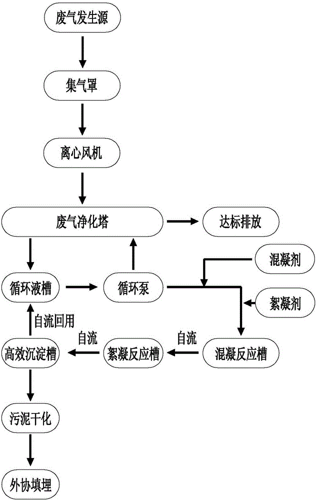
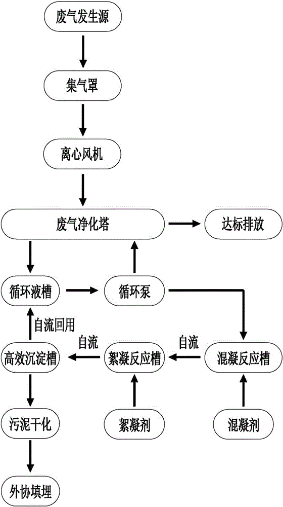
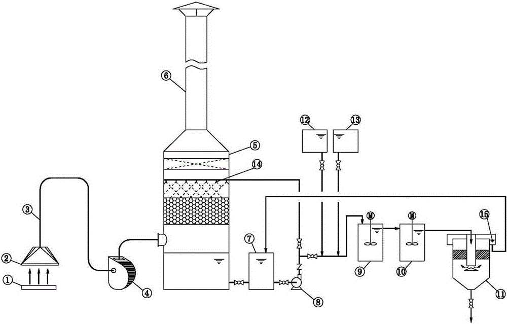
[0024] like Figure 1-3 Shown: a waste gas purification treatment process for reuse of internal circulating fluid, the steps of the purification treatment process are: (1) The target treatment waste gas generated by the waste gas generation source 1 is driven by the gas collecting hood 2 under the power provided by the centrifugal fan 4 After being collected, it is transported to the exhaust gas purification tower 5 through the main air pipe 3, and the exhaust gas flows from the bottom of the exhaust gas purification tower 5 from bottom to top, and the circulating liquid in the circulating liquid tank 7 is lifted by the circulating pump 8 to the spray mechanism 14 in the exhaust gas purification tower 5 , the spray mechanism 14 sprays the waste gas from the top to the bottom against the air flow, and the target pollutants in the waste gas are purified u...


PUM


Abstract

The invention discloses a waste gas purifying treatment technology for reusing an internal circulation solution. The purifying treatment technology comprises the following steps: 1, collecting target treatment waste gases generated by a waste gas generation source by a gas collection hood, and conveying the collected waste gases to a waste gas purifying tower through a main gas tube, and allowing the waste gases to upward flow from the lower portion of the waste gas purifying tower and to be purified by a downward flowing circulation solution, wherein the circulation solution is repeatedly recycled until saturation and failure; and 2, lifting a failure circulation solution in a circulation solution tank to a coagulation reaction tank through a circulating pump, carrying out a coagulation reaction, allowing the coagulated failure circulation solution to automatically flow into a flocculation reaction tank, carrying out a flocculation reaction, allowing the flocculated solution to automatically flow into a high efficiency sedimentation tank, and allowing the purified circulation solution to flow into the circulation solution tank. The failure circulation solution is coagulated, flocculated and deposited to obtain the purified circulation solution, and the purified circulation solution is reused, so the cost is saved, pollution is reduced, and energy saving and emission reduction requirements are met; and the technology also has the advantages of concise flow, stable recycling and small occupied area.

Description

technical field [0001] The invention relates to the field of waste gas treatment, in particular to waste gas treatment in machinery industry or foundry industry, in particular to a waste gas purification treatment process for reusing internal circulating liquid. Background technique [0002] Exhaust gas purification widely exists in machinery, foundry, electronics and other industries. At present, many manufacturers in the machining, casting and electronics industries are accompanied by excessive waste gas and dust in the production process. The general treatment method of such manufacturers is to use the traditional wet spray method, that is, to use the circulating spray liquid in the purification tower. Reverse physical impact or chemical neutralization and oxidation are carried out on the exhaust gas to make the exhaust gas discharge up to the standard, and the excessive pollutants in the exhaust gas are brought into the circulating fluid. When the circulating fluid reac...

Claims


Application Information

Patent Timeline
IPC IPC(8): B01D53/78B01D53/96
Inventor 李碧强蔡君军
Owner JIANGSU NANFANG COATING & ENVIRONMENT PROTECTION EQUIP
Why Eureka
Eureka Blog
Learn More