Deflection error compensation method for five-axis machining center tool

A five-axis machining center, deformation error technology, applied in metal processing, manufacturing tools, metal processing equipment and other directions, can solve the problem of inapplicability of tool deformation error compensation, and achieve the effect of improving manufacturing accuracy

Inactive Publication Date: 2016-01-13
TIANJIN UNIV
View PDF5 Cites 26 Cited by
  • Summary
  • Abstract
  • Description
  • Claims
  • Application Information

AI Technical Summary

Problems solved by technology

[0006] The tool deformation error compensation method proposed in literature (1) (2) is mainly for three-axis machining, and is not applicable to tool deformation error compensation for five-axis machining
[0007] The error compensation model established in literature (3) considers the geometric error in the machine tool movement process, but does not involve the tool deformation error in the five-axis machine tool machining process.

Method used


Image

  • Deflection error compensation method for five-axis machining center tool
  • Deflection error compensation method for five-axis machining center tool
  • Deflection error compensation method for five-axis machining center tool

Examples


Embodiment Construction

[0026] In order to make the purpose, technical solution and advantages of the present invention clearer, the implementation manners of the present invention will be further described in detail below.

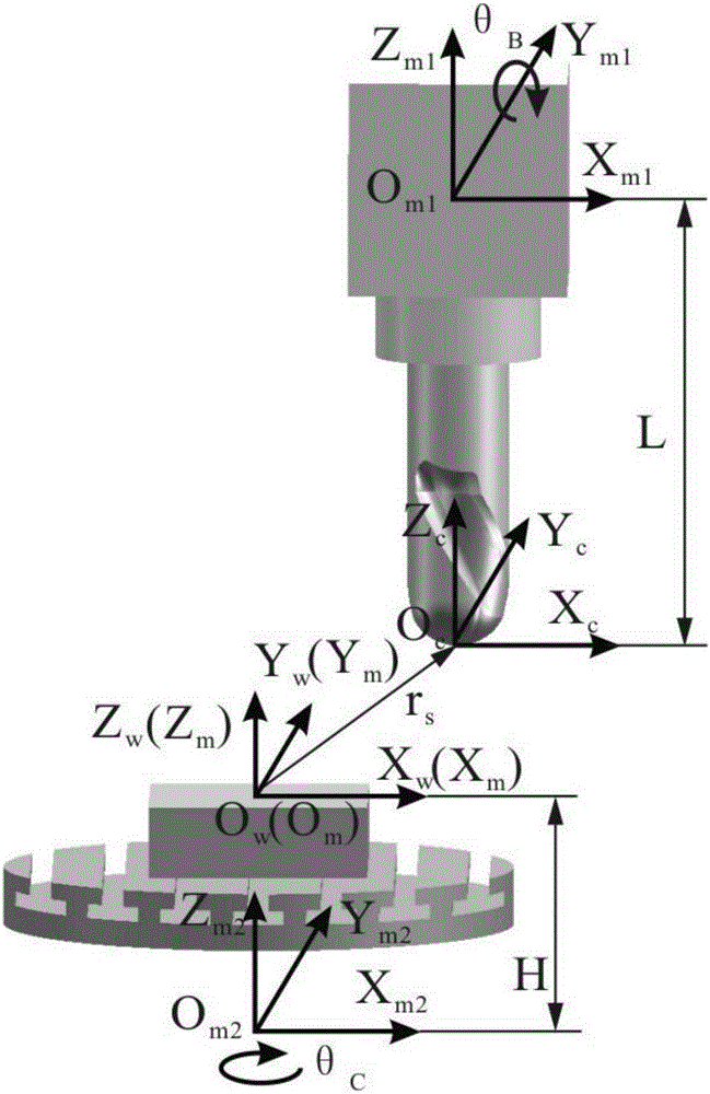
[0027] The specific implementation of the embodiment of the present invention will be described in detail below in conjunction with the accompanying drawings, taking the milling of the ball end of the five-axis linkage machine tool with the B swing head and the C turntable as an example.

[0028] 101: Establish the mutual conversion relationship between the tool coordinate system, workpiece coordinate system and machine tool coordinate system, and obtain the motion parameters of the machine tool during five-axis machining;

[0029] The embodiment of the present invention takes a five-axis CNC machine tool with C turntable and B swing head structure as an example, analyzes the kinematic relationship between coordinates, and establishes the conversion relationship between the tool ...


PUM


Abstract

The invention discloses a deflection error compensation method for a five-axis machining center tool. The deflection error compensation method includes the steps that the milling force is computed according to a built five-axis machining milling force model; the theoretical tool location point and a tool-axis vector serve as the benchmark of mirror image reversible deflection compensation; the tool deflection error, caused by the milling force, of the current tool position is worked out according to the tool deflection; mirror image reversible deflection compensation is conducted on the current tool location point and the tool-axis vector, and a new tool location point and a new tool-axis vector are worked out according to the tool deflection error; a new tool deflection error is computed according to the compensated tool location point data, and whether the new error exists or not is judged; if the requirement is met, operation is stopped, and the tool location point information is stored; and the compensated tool location point data information corresponding to the tool path positions from 1 to N is collated, accordingly the compensated tool location locus is obtained, and a compensated numerical control program is generated through post-processing software.

Description

technical field [0001] The invention relates to the technical field of numerical control machining, in particular to a tool deformation error compensation method for a five-axis machining center. Background technique [0002] In the actual processing process, the milling system is generally composed of machine tools, tools, fixtures, and workpieces. The rigidity of the machine tools and fixtures is generally considered to be sufficient, and the deformation of the workpiece (non-thin-walled parts) is relatively small. The rigidity of the tool is relatively fragile, and the deformation of the tool in the milling system is an unavoidable problem, especially when using a "slender rod" tool for processing, the deformation of the tool cannot be ignored, and it is prone to bending under the action of cutting force Deformation is the main factor causing the geometric error of the machined surface. Five-axis linkage CNC technology has unique advantages in the processing of complex s...

Claims


Application Information

Patent Timeline
Patent Type & Authority Applications(China)
IPC IPC(8): B23Q15/12
CPCB23Q15/12
Inventor 何改云马文魁丁伯慧黄鑫
Owner TIANJIN UNIV
Why Eureka
Try Eureka