
Micro-nano fiber yarn spinning device and spinning process thereof

A micro-nano fiber, yarn technology, applied in yarn, melt spinning, textile and papermaking, etc., can solve problems such as production reduction

Active Publication Date: 2016-01-13
新疆天棉基业纺织有限公司
View PDF4 Cites 11 Cited by
  • Summary
  • Abstract
  • Description
  • Claims
  • Application Information

AI Technical Summary

Problems solved by technology

The finer the fiber, the better the quality of the melt blown cloth, but the output is relatively reduced

Method used

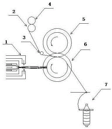

Image

  • Micro-nano fiber yarn spinning device and spinning process thereof
  • Micro-nano fiber yarn spinning device and spinning process thereof
  • Micro-nano fiber yarn spinning device and spinning process thereof

Examples


Embodiment 1

[0047] A single-hole melt-blown testing machine is used, the width of the air groove is 0.65mm; the angle of the air groove is 30°; the diameter of the spinneret hole is 0.42mm, and the spinneret process is: the temperature of the polymer melt is 260°C, and the temperature of the hot air is 280°C , the air pressure is 0.3MPa, the receiving distance is 10cm, the melt flow rate of the PP polymer used is 900g / 10min, and the diameter of the spinning fiber is between 0.6-1.1μm.

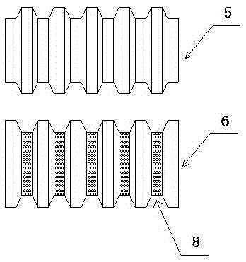
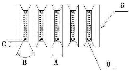
[0048] Spinning process parameters: polyester DTY40D / 96f filament is used, the diameter of the upper and lower drums is 100mm, the rotational speed of the upper and lower drums is 3500mm / min, and the surfaces of the upper and lower drums are "V" shaped Groove structure, the width A of the groove top is 30mm, the angle B is 90°, the groove depth C is 10mm, the diameter of the microhole is 1mm, and the density of the hole is 25 / cm 2 , The negative pressure on the bottom surface of the lower drum groove is: 100...

Embodiment 2

[0050] A single-hole meltblown test machine is used, the air groove width is 0.65mm; the air groove angle is 30°; the spinneret hole diameter is 0.42mm. The spinning process is: the polymer melt temperature is 240°C; the air pressure is 0.3MPa; the receiving distance is 15cm, the hot air temperature is 280°C, the melt flow rate of the PP polymer used is 900g / 10min, and the average diameter of the spinning fiber is is 1.2 μm.

[0051] Spinning process parameters: the spandex yarn is 70D, the spandex yarn tension is 4.1 times, the diameter of the upper drum and the lower drum is 100mm, the rotation speed of the upper drum and the lower drum is 3000mm / min, the upper drum and the lower drum are The surface is a "V" groove structure, the width A of the groove top is 30mm, the angle B is 90°, the groove depth C is 10mm, the diameter of the micropore is 0.8mm, and the density of the hole is 36 / cm 2 , The negative pressure on the bottom surface of the lower drum groove is: 60Pa. For...


PUM

PropertyMeasurementUnit
Groove depthaaaaaaaaaa
Diameteraaaaaaaaaa

Abstract

The invention discloses a micro-nano fiber yarn spinning device and a spinning process thereof. The micro-nano fiber yarn spinning device comprises a spinning jet, a yarn feeding system, a fiber polymerization mechanism and a twisting mechanism, wherein the spinning jet is composed of a hot air pipe, a polymer melt pipe and a cold air pipe, the yarn feeding system is composed of cheese yarns, an unwinding roller and a yarn guide rod, the fiber polymerization mechanism is composed of an upper roller and a lower roller which are mutually connected in a meshed mode, a plurality of micro-pores are formed in the bottom of the groove of the lower roller, and an irregular air pipe is further arranged inside the lower roller. The micro-nano fiber yarn spinning device is reasonable in structure and process design, convenient to operate actually and capable of spinning micro-nano fiber sprayed out of the melting-spraying spinning jet into micro-nano fiber core spun yarns, the micro-nano fiber wraps the surfaces of core yarns, and the attachment rate and the working efficiency are high, so that produced yarns have the functions of microbial resistance, heat insulation, heat preservation, filtering and adsorption, sound absorption and the like.

Description

technical field [0001] The invention relates to a spinning device and a process thereof, in particular to a micro-nano fiber yarn spinning device and a spinning process thereof. Background technique [0002] Melt blown spinning technology is mainly used in the production of nonwovens. Flame-blown nonwoven technology originated in the early 1950s, when the U.S. Naval Laboratory, with government funding, researched and developed filter materials for collecting radioactive particles in the upper atmosphere after nuclear bomb explosions. Extruded into a concentrated hot air flow through the extruder, the ultra-fine fibers formed under the stretching effect of the air flow are blown to the condenser, thereby accumulating into an ultra-fine filter material. This process is the prototype of modern meltblown nonwoven technology. In the mid-1960s, the American Exxon company improved the method, and in the 1970s, it turned this technology into civilian use, and jointly established a...

Claims


Application Information

Patent Timeline
IPC IPC(8): D01D5/08D02G3/36
Inventor 刘梅城洪杰
Owner 新疆天棉基业纺织有限公司
Learn More