Supercharge Your Innovation With Domain-Expert AI Agents!

Integrated anti-floating structure of underground diaphragm wall and concrete structure bottom plate and construction method of integrated anti-floating structure

An underground diaphragm wall and concrete structure technology, applied in underwater structures, infrastructure engineering, excavation, etc., can solve the problems of long construction period, short construction period, cumbersome procedures, etc., and achieve the effect of large amount of engineering and guaranteeing stability.

Active Publication Date: 2016-01-13
SUZHOU UNIV
View PDF5 Cites 6 Cited by
  • Summary
  • Abstract
  • Description
  • Claims
  • Application Information

AI Technical Summary

Problems solved by technology

[0005] The present invention aims at the construction process of the existing foundation pit, in the design of anti-pit bottom uplift and anti-permanent structural buoyancy, respectively adopts techniques such as filling concrete and anti-lift piles or constructing box top pressure beams, and fails to make full use of the existing underground continuous The anti-lifting performance of the wall has problems such as cumbersome procedures, long construction period, and high cost. Provide an underground continuous wall that can effectively prevent foundation pit surges, ensure the anti-floating of the permanent structure, and have a short construction period and low cost. Integral anti-floating structure with interlocking concrete base plates and its construction method

Method used


Image

  • Integrated anti-floating structure of underground diaphragm wall and concrete structure bottom plate and construction method of integrated anti-floating structure

Examples


Embodiment 1

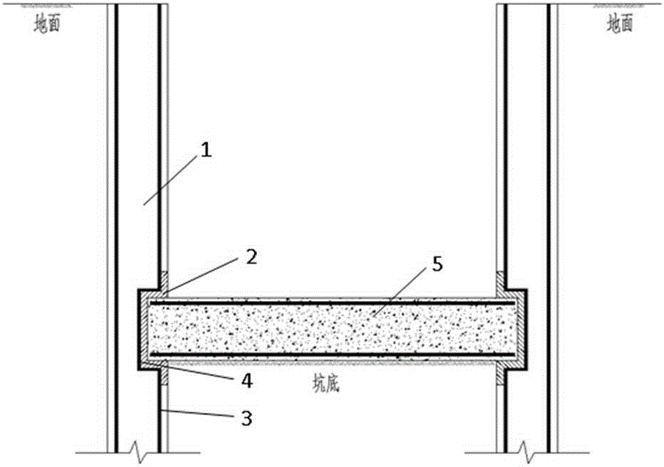
[0020] See attached figure 1 , which is a schematic cross-sectional view of an overall anti-floating structure in which an underground diaphragm wall and a concrete floor are embedded with each other provided in this embodiment; , the reinforcement cage and the U-shaped steel are fixed through the welding point 4, and the two ends of the concrete structure bottom plate 5 are respectively placed in the steel grooves of the U-shaped steel, so that the underground diaphragm wall and the concrete bottom plate form an integral anti-floating structure embedded with each other. In this structure, the underground continuous wall used for excavation and maintenance of deep foundation pit and the concrete bottom plate used for the permanent structure in the foundation pit are embedded with each other through steel grooves, so that the ground continuity and the structural bottom plate form an integral force-bearing structure, thus, in the foundation pit During the excavation process, the...


PUM


Abstract

The invention discloses an integrated anti-floating structure of an underground diaphragm wall and a concrete structure bottom plate and a construction method of the integrated anti-floating structure. When an underground diaphragm wall reinforcement cage is manufactured on the ground, the portion on the side, close to a foundation pit, of the reinforcement cage is bent into a U shape, and U-shaped structural steel is welded to the reinforcement cage; after the underground diaphragm wall is grooved, the structural steel is placed in the foundation bottom elevation in an underground diaphragm wall groove together with the reinforcement cage, and underground diaphragm wall concrete is poured; and after the foundation pit is excavated to the bottom, the reinforcement cage of the structure bottom plate is embedded in grooves of the U-shaped structural steel on the two sides of the foundation pit, and then the reinforced concrete structure bottom plate is poured. The underground diaphragm wall used for excavating and maintaining of the deep foundation pit and the concrete bottom plate for a permanent structure in the foundation pit are embedded and connected through the structural steel grooves, an integral stress structure is formed, the stability of the pit bottom in the excavating process can be guaranteed, and the anti-floating requirement of the permanent structure can be met as well. The integrated anti-floating structure has the beneficial effects that the work period is shortened, the engineering cost is reduced, and construction risks are reduced.

Description

technical field [0001] The invention relates to an integral anti-floating structure technology during excavation of a foundation pit, in particular to an integral anti-floating structure in which an underground continuous wall and a concrete floor are embedded with each other and a construction process thereof. Background technique [0002] With the deep development of underground space structure, the excavation depth of foundation pit has been increasing continuously in recent years. Due to its excellent waterproof sealing and bending resistance, the underground diaphragm wall is the most commonly used enclosure structure for deep foundation pit excavation in water-rich soft soil areas. During the excavation of deep foundation pits, due to the unloading effect caused by the excavation of the soil in the pit and the seepage effect caused by the unbalanced water head inside and outside the pit, the soil at the bottom of the pit often bulges, and groundwater seepage drives a l...

Claims


Application Information

Patent Timeline
IPC IPC(8): E02D31/12E02D29/045E02D17/04
Inventor 史培新唐强李攀刘维许东风陈丽娟俞蔡城张洁
Owner SUZHOU UNIV
Features
  • R&D
  • Intellectual Property
  • Life Sciences
  • Materials
  • Tech Scout
  • Unparalleled Data Quality
  • Higher Quality Content
  • 60% Fewer Hallucinations
Learn More