Radar captive carrying test position parameter automatic binding method based on measurement and control equipment

A technology of test position and measurement and control equipment, which is applied in the direction of radio wave measurement system, navigation through speed/acceleration measurement, instruments, etc., can solve the problem of poor binding reliability, error between actual position parameters and binding position parameters, low binding efficiency, etc. Problems, to avoid human binding errors, high precision, high binding efficiency

Inactive Publication Date: 2016-01-13
SHANGHAI RADIO EQUIP RES INST
View PDF4 Cites 5 Cited by
  • Summary
  • Abstract
  • Description
  • Claims
  • Application Information

AI Technical Summary

Problems solved by technology

[0006] During the hang-up test, there is a deviation between the flight route of the carrier aircraft and the planned route, which will directly lead to the deviation between the actual start point and the scheduled start point, and then cause an error between the actual position parameters and the binding position parameters
Since the deviation between the flight route and the planned route is uncontrollable, the parameter binding error is also uncontrollable
[0007] 2. The efficiency of parameter binding is low
[0008] With the method of manual parameter binding, the operator needs to input all position parameters into the measurement and control equipment one by one in sequence, which cannot realize simultaneous binding of all parameters, and the binding efficiency is low
If there is a short distance between the two start-up points, due to low efficiency, it is easy to miss the start-up point
Even if the distance between the two start-up points is sufficient, there will be a large error between the binding parameters and the actual start-up point due to factors such as human reaction time and operation delay during manual operation.
[0009] 3. The error probability of parameter binding is high
[0010] Manual parameter binding is prone to errors such as filling in data errors, parameter binding misplacement, etc., the probability of error is high, and the binding reliability is not strong
[0011] The above three shortcomings of the manual binding position parameters will seriously affect the success probability and credibility of the flying test
[0012] In the prior art, "Analysis of the Influence of Target Indication Information Delay on Binding of Anti-ship Missile Terminal Guidance Radar Parameters" published in "Journal of Missiles and Guidance" in Volume 33, Issue 1 in February 2013 discloses a search sector method , based on this method, the terminal guidance radar binding parameters can be calculated to shorten the influence of target indication information delay on parameter binding, but it does not mention the use of measurement and control equipment to complete the calculation process, let alone the automatic binding method of measurement and control equipment
As another example, in 2013 Harbin Institute of Technology's master's degree thesis "Development of a Radar Flying Test Measurement and Control Equipment", disclosed a method of developing a radar flying test measurement and control equipment, and mentioned that the measurement and control equipment can calculate radar inertial navigation through GPS information. Data, through the inertial navigation data to further obtain the azimuth, elevation angle and distance of the target relative to the radar, but there is no mention of the automatic binding function of the measurement and control equipment, let alone mention that in the radar system that needs speed compensation, the carrier aircraft "east speed ", "Northward speed" and "Airward speed" (referred to as "Northeast sky" three-way speed) calculation and automatic binding

Method used


Image

  • Radar captive carrying test position parameter automatic binding method based on measurement and control equipment
  • Radar captive carrying test position parameter automatic binding method based on measurement and control equipment
  • Radar captive carrying test position parameter automatic binding method based on measurement and control equipment

Examples


Embodiment Construction

[0046] The present invention will be further elaborated below by describing a preferred specific embodiment in detail in conjunction with the accompanying drawings.

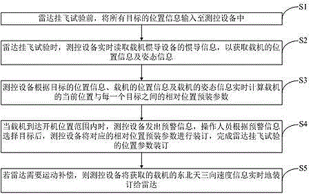
[0047] Such as figure 1 As shown, a method for automatically binding the position parameters of the radar flying test based on the measurement and control equipment includes the following steps:

[0048] S1. Before the radar flight test, input the position information of all targets into the measurement and control equipment;

[0049] S2. During the radar flying test, the measurement and control equipment reads the inertial navigation information of the carrier aircraft's inertial navigation equipment in real time to obtain the position information and attitude information of the carrier aircraft;

[0050] S3. The measurement and control equipment calculates the relative position pre-installed parameters between the current position of the carrier aircraft and each target in real time according to the position i...


PUM


Abstract

The invention discloses a radar captive carrying test position parameter automatic binding method based on measurement and control equipment. The method comprises the following steps: before the radar captive carrying test, position information of all targets is inputted to the measurement and control equipment; in the case of the radar captive carrying test, the measurement and control equipment reads inertial navigation information of aerial carrier inertial navigation equipment in real time to acquire position information and gesture information of the aerial carrier; according to the target position information, the aerial carrier position information and the aerial carrier gesture information, the measurement and control equipment calculates relative position pre- binding parameters between the aerial carrier current position and each target; and when the aerial carrier arrives in an opening position range, the measurement and control equipment gives early warning information, an operator selects a target according to the early warning information, the measurement and control equipment binds the corresponding relative position pre-binding parameters, and position parameter binding of the radar captive carrying test is completed. The binding parameters are complete, binding errors are controllable, the binding efficiency is high, the error rate is low, and guarantee is provided for radar search and interception precision.

Description

technical field [0001] The invention relates to the technical field of testing, in particular to a method for automatically binding position parameters of a radar flying test based on measurement and control equipment. Background technique [0002] During the radar flying test, in order to ensure that the radar can correctly search and intercept the target, it is necessary to bind the parameters such as the "azimuth installation angle", "pitch installation angle" and "relative distance" of the radar relative to the target before starting the machine. [0003] The current method of parameter binding is mostly manual, that is, the radar start-up point for the flight test is set in advance, and the "azimuth angle" and "azimuth angle" between the radar at the start-up point and the target are calculated according to the start-up point and the position information of the target. Pitch angle" and "relative distance" and other parameter information. Then manually input the above p...

Claims


Application Information

Patent Timeline
Patent Type & Authority Applications(China)
IPC IPC(8): G01S7/40G01C21/16
CPCG01C21/16G01S7/40
Inventor 蔡信余渝生王志诚张天键田原
Owner SHANGHAI RADIO EQUIP RES INST
Why Eureka
Try Eureka