Image sensor chip packaging structure and packaging method

An image sensor chip and packaging structure technology, applied in the semiconductor field, can solve problems such as virtual connection and breakage, and achieve the effects of improving integration, realizing miniaturization, and preventing virtual connection or even breaking.

Active Publication Date: 2019-02-26
CHINA WAFER LEVEL CSP
View PDF2 Cites 2 Cited by
  • Summary
  • Abstract
  • Description
  • Claims
  • Application Information

AI Technical Summary

Problems solved by technology

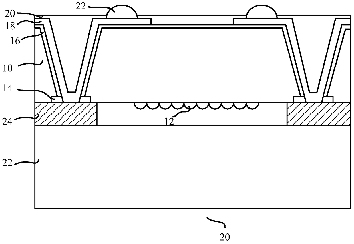
[0004] However, in this structure, the electrical connection layer 18 is arranged between the solder resist layer 20 and the insulating layer 16, and the insulating layer 16 is mostly formed of organic materials. There will be temperature changes in the follow-up reliability test. After the solder resist layer 20 and the insulating layer 16 expand, the electrical connection layer will be squeezed, making it prone to defects such as virtual connections or even fractures.

Method used


Image

  • Image sensor chip packaging structure and packaging method
  • Image sensor chip packaging structure and packaging method
  • Image sensor chip packaging structure and packaging method

Examples


Embodiment Construction

[0046] In order to make the above objects, features and advantages of the present invention more comprehensible, specific implementations of the present invention will be described in detail below in conjunction with the accompanying drawings.

[0047] In the following description, a lot of specific details are set forth in order to fully understand the present invention, but the present invention can also be implemented in other ways different from those described here, and those skilled in the art can do it without departing from the meaning of the present invention. By analogy, the present invention is therefore not limited to the specific examples disclosed below.

[0048] Secondly, the present invention is described in detail in combination with schematic diagrams. When describing the embodiments of the present invention in detail, for the convenience of explanation, the cross-sectional view showing the device structure will not be partially enlarged according to the gener...


PUM


Abstract

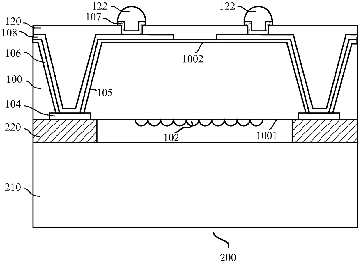
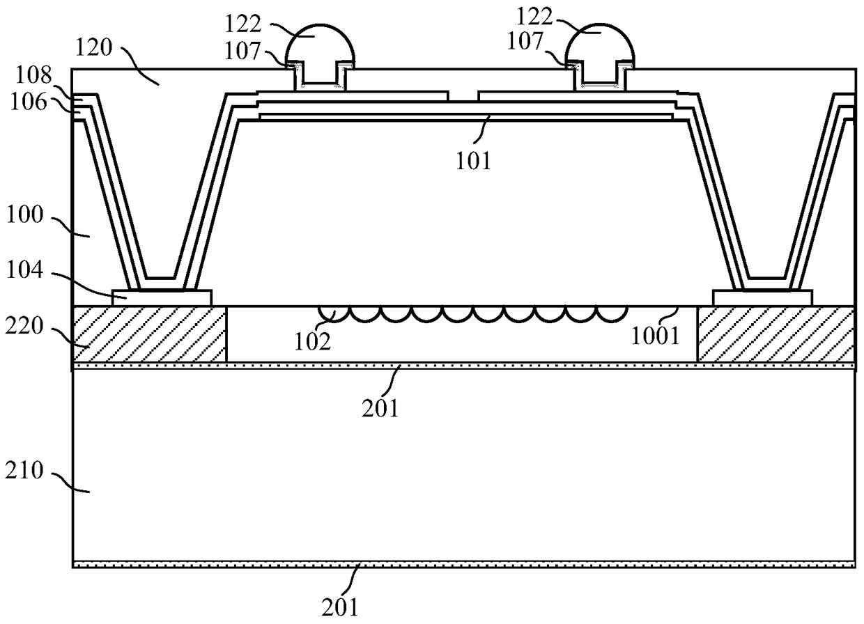
The present invention provides an image sensor chip packaging structure, comprising: an image sensor chip, which has a first surface and a second surface opposite to each other, an image sensing area is arranged on the first surface and is located around the image sensing area The welding pad; the through hole penetrating from the second surface to the welding pad; the electrical wiring layer arranged along the inner wall of the through hole and extending to the second surface, and the electrical wiring layer is electrically connected to the welding pad; filling the through hole And cover the solder resist layer of the electrical connection layer, an opening is formed in the solder resist layer, and the bottom of the opening exposes the electrical connection layer; the guide covering the inner wall of the opening and the bottom of the opening and extending to the solder resist layer Welding pads, the guiding welding pads are electrically connected to the electrical wiring layer; welding bumps located on the guiding welding pads, the welding bumps are electrically connected to the guiding welding pads. The structure reduces defects in the electrical wiring layer of the image sensor chip.

Description

technical field [0001] The invention relates to the technical field of semiconductors, in particular to an image sensor chip packaging structure and packaging method. Background technique [0002] At present, wafer level packaging (Wafer Level Packaging) technology is the technology of testing and packaging the whole wafer and then cutting it to obtain a single finished chip. It gradually replaces the wire bonding packaging technology and becomes the mainstream technology of packaging. [0003] In the packaging of image sensors, wafer-level packaging technology is often used, such as figure 1 as shown in figure 1 As shown, it is an existing conventional image sensor packaging structure, which includes an image sensor chip 10 and a protective cover plate 20, an image sensor region 12 and a welding pad 14 are arranged on the first surface of the image sensor chip, and the protective cover The plate 20 is arranged above the image sensing region 12 to protect the image sensing...

Claims


Application Information

Patent Timeline
Patent Type & Authority Patents(China)
IPC IPC(8): H01L27/146
Inventor 王之奇王卓伟谢国梁
Owner CHINA WAFER LEVEL CSP
Why Eureka
Try Eureka