Beam detection device

A detection device and beam current technology, which is applied in the direction of discharge tubes, electrical components, circuits, etc., can solve the problems of high installation space requirements, difficult wiring, and poor real-time performance, and achieve dense settings, reduce requirements, and improve stability. Effect

Pending Publication Date: 2018-10-02
KINGSTONE SEMICONDUCTOR LIMITED COMPANY +1
View PDF0 Cites 4 Cited by
  • Summary
  • Abstract
  • Description
  • Claims
  • Application Information

AI Technical Summary

Problems solved by technology

[0010] The technical problem to be solved by the present invention is to overcome the defects of high installation space requirements, difficult wiring, and poor real-time performance of the large-size beam detection device in the prior art, and to provide a large-size beam detection device with better real-time performance. , A beam detection device with low installation space requirements

Method used


Image

  • Beam detection device
  • Beam detection device
  • Beam detection device

Examples


Embodiment 1

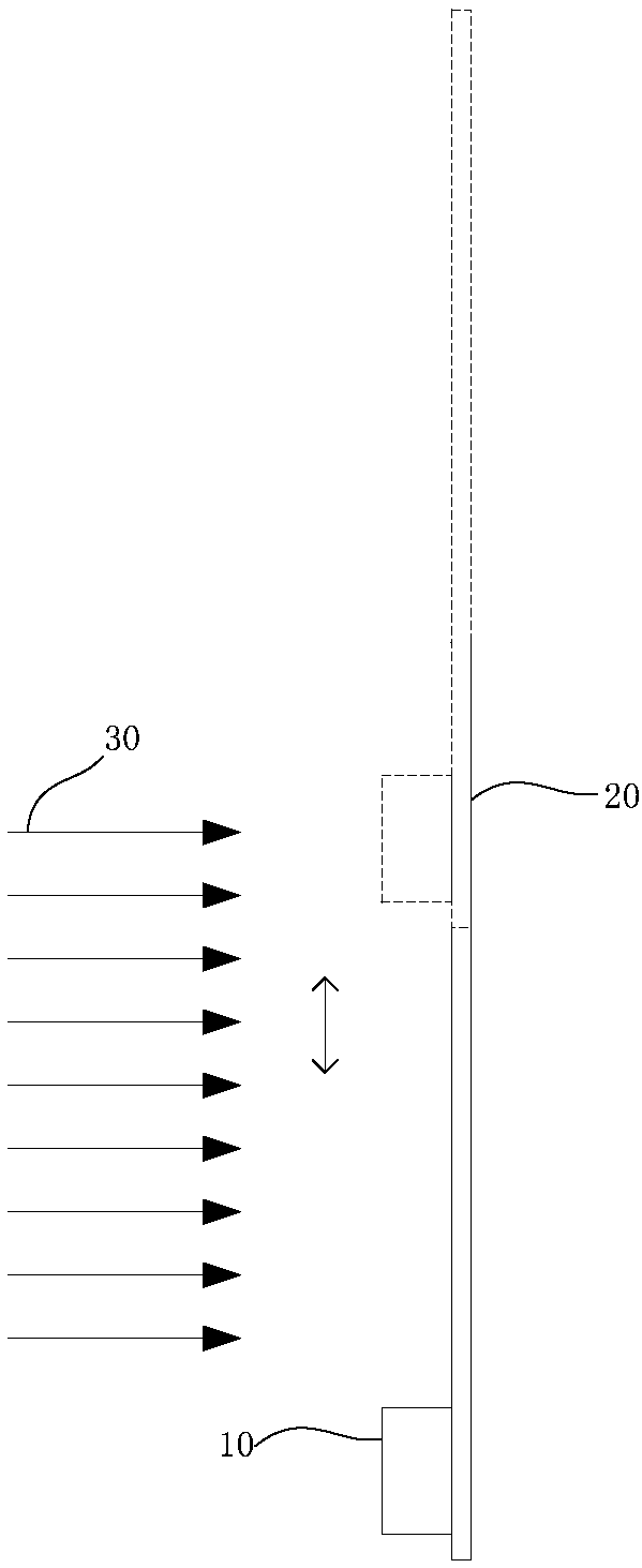
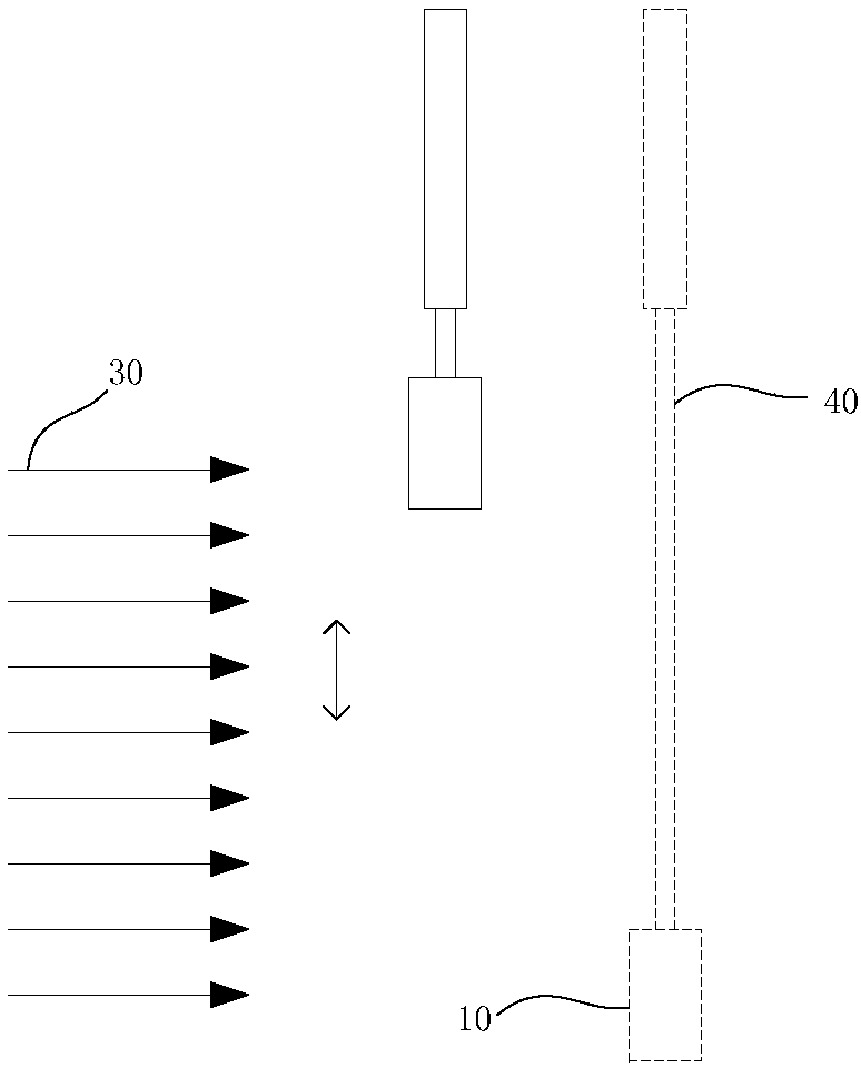
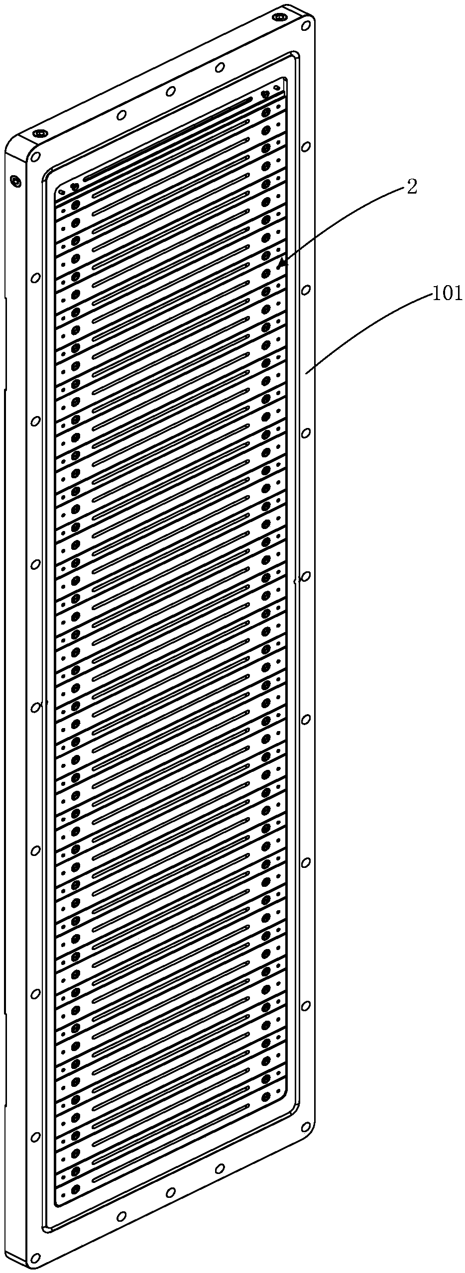
[0049] refer to Figure 3-Figure 13 , introduce the beam detection device described in this embodiment, the beam to be detected is a ribbon beam (ribbon beam), the long side direction of the beam is the y-axis direction, the short side direction of the beam is the x-axis, and the beam The transmission direction of the stream is the z-axis (for the simplicity of the illustration, the coordinate system is only in Figure 7 with Figure 8 Marked in ), the beam detection device is fixed to the cavity wall of a vacuum chamber, the cavity wall includes the atmosphere side 102 located in the atmosphere environment and the vacuum side 101 located in the vacuum environment, the cavity wall is provided with parallel arrays A plurality of first through holes 11, the arrangement direction of the plurality of first through holes 11 is consistent with the long side direction of the beam to be detected, the beam detection device includes: a plurality of Faradays arranged in parallel at inte...


PUM


Abstract

The invention discloses a beam detection device. The beam detection device is fixed to the cavity wall of a vacuum cavity; and a plurality of first through holes located in parallel are formed in thecavity wall. The beam detection device comprises a plurality of parallelly-arranged Faraday cups which are distributed at intervals and fixed to an atmosphere side; a surface of the cup body of each Faraday cup, which contacts the atmosphere side, is insulated; each Faraday cup is provided with a conductive portion for receiving a beam; the Faraday cups are located at a magnetic field; and the magnetic field is used for enabling electrons in a beam to be detected to strike the cavity wall when the electrons bypass magnetic lines of force. According to the beam detection device of the invention, a fixed beam detection mode is adopted; the plurality of Faraday cups arranged along the long side direction of the beam are adopted to obtain the current values of sampling points in the lone sidedirection of the beam, so that the various parameters of the beam can be obtained; and the problem of high requirements for equipment installation space, a vacuum sealing problem which is caused by vacuum force transmission and the problem of difficulty in wiring of a mobile beam detection device in large-sized beam detection can be solved.

Description

technical field [0001] The invention relates to a detection device, in particular to a beam current detection device. Background technique [0002] In order to obtain parameters such as the shape of the beam and the magnitude of the current, the ion implanter is equipped with a beam profiler. Usually, the beam profiler is located downstream of the beam transmission path and close to the implantation station. Generally, the beam detection device includes a beam receiving part and a test instrument (such as an ammeter) connected to the beam receiving part. [0003] Such as figure 1 with figure 2 Shown is a beam current detection device for a ribbon beam in an ion implanter for solar cell manufacturing and an integrated circuit ion implanter, figure 1 The beam detection device 10 is connected with the guide rod 20, and can move up and down in the direction of the arrow. When the beam current 30 needs to be detected, the guide rod 20 can move along the guide rail (not shown ...

Claims


Application Information

Patent Timeline
Patent Type & Authority Applications(China)
IPC IPC(8): H01J37/244H01J37/317
CPCH01J37/244H01J37/3171
Inventor 张晓峰金浩
Owner KINGSTONE SEMICONDUCTOR LIMITED COMPANY
Why Eureka
Try Eureka