Check patentability & draft patents in minutes with Patsnap Eureka AI!

Inverter control device

A control device, inverter technology, applied in control systems, motor control, control/regulation systems, etc., to achieve the effect of reducing power consumption

Inactive Publication Date: 2018-05-04
SHARP KK
View PDF6 Cites 0 Cited by
  • Summary
  • Abstract
  • Description
  • Claims
  • Application Information

AI Technical Summary

Problems solved by technology

[0008] Patent Document 1 discloses that the motor is decelerated by reducing the frequency of the inverter when the amount of sunlight decreases, but there is no description on how to control the motor so that the motor does not stop.

Method used


Image

  • Inverter control device
  • Inverter control device
  • Inverter control device

Examples


Embodiment approach 1

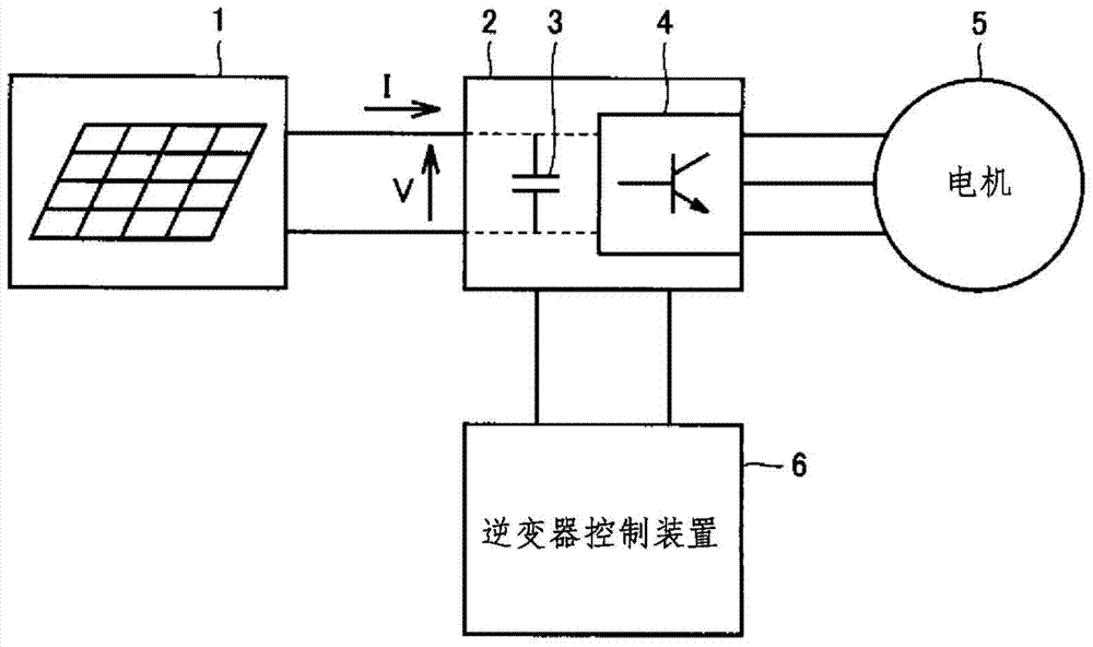
[0032] As an example of the power conversion system according to Embodiment 1 of the present invention, figure 1 As shown, a solar cell 1 , an inverter 2 , a motor 5 and an inverter control device 6 are provided. The solar cell 1 converts solar energy into direct current as a power generating element. The inverter 2 is controlled by the inverter control device 6, and converts the direct current generated by the solar battery 1 into an alternating current with adjustable frequency and voltage. The inverter 2 includes: a smoothing capacitor 3 that smoothes the output voltage V of the solar cell 1 ; and a switching element 4 that is on / off-controlled by an inverter control device 6 .

[0033] The motor 5 is driven by the alternating current generated at the inverter 2 for driving a compressor and a pump of a refrigerator, for example. The motor 5 may be a synchronous motor that is rotationally driven at a rotational speed corresponding to the frequency of the alternating curren...

Embodiment approach 2

[0062] Figure 9 and Figure 10 is a timing chart showing the operation of the inverter control device included in the power conversion system according to Embodiment 2 of the present invention, and is and Figure 4Comparison chart. The previous stable control mode is executed at times t0 to t1, and the motor 5 is rotationally driven at a certain fixed rotational speed Rn. At time t1, the inverter control device detects the output voltage V0 of the solar battery 1, determines the next target rotation speed R(n+1) (for example, 2250 rpm) according to the current rotation speed Rn (for example, 2000 rpm), and switches to the acceleration control mode. In addition, the rotational speed between Rn and R(n+1), for example, [Rn+R(n+1)] / 2 is set as the threshold rotational speed RTH (at this time, 2125 rpm).

[0063] When the inverter control device is in the acceleration control mode, while increasing the rotational speed of the motor 5 from Rn to R(n+1), it detects the output vo...

Embodiment approach 3

[0081] In Embodiments 1 and 2, in the acceleration control mode, the rotational speed of the motor 5 is increased by a predetermined rotational speed each time, and the output voltage V1 of the solar battery 1 is detected each time, and the voltage variation ΔV=V0-V1 is obtained, and compared ΔV and the magnitude of the threshold voltage VTH. For example, the output voltage V1 of the solar cell 1 is detected every time the rotation speed is increased by a scale amount of 10 rpm, and the voltage change amount ΔV=V0-V1 is obtained. In this way, since the current rotation speed R can be accurately detected, the comparison between the target rotation speed of the current rotation speed R and the threshold rotation speed can be performed more accurately.

[0082]On the other hand, in the deceleration control mode, it is necessary to quickly restore the power supply capability of the solar battery 1 to ample, so it is preferable to end the deceleration as early as possible. However...


PUM


Abstract

The inverter control device (6) of the present invention includes: a stable control mode, which rotates and drives the motor (5) at a selected rotational speed (Rn) among the rotational speeds (R1~RN) of the N gear; an acceleration control mode, which makes the motor The rotational speed of (5) increases towards the target rotational speed (R(n+1)) which is one gear higher than the selected rotational speed (Rn); in the deceleration control mode, the rotational speed of the motor (5) is increased towards the target rotational speed in the acceleration control mode. The rotational speed (R(n+1)) is lower than the rotational speed (R(n‑1)) of the second gear decreases, and when the variation (ΔV) of the output voltage (V) of the solar cell (1) exceeds the threshold voltage in the acceleration control mode (VTH), switch from acceleration control mode to deceleration control mode. This reduces the power consumption of the motor (5), so it is possible to avoid stopping the motor (5) due to insufficient power supply.

Description

technical field [0001] The present invention relates to an inverter control device, in particular to an inverter control device for controlling a motor by means of an inverter. Background technique [0002] According to the inverter control method, the inverter converts direct current into alternating current of a desired frequency, and uses the alternating current to drive the motor to rotate at a desired rotational speed. The power consumption of the motor changes according to the rotation speed, so the inverter control method is used in products that require energy saving, such as refrigerator compressors. In addition, the inverter control method is also used in motors driven by power sources whose power supply varies, such as solar cells, such as water pumps in non-electrified areas. [0003] For example, Japanese Patent Laid-Open Publication No. 2003-195957 (Patent Document 1) discloses an inverter control device that detects the DC power and DC voltage output from the...

Claims


Application Information

Patent Timeline
Patent Type & Authority Patents(China)
IPC IPC(8): H02P27/06G05F1/67H02M7/48
CPCG05F1/67H02P23/00H02P29/10H02P2205/03
Inventor 石住隆司今出雅士
Owner SHARP KK
Features
  • R&D
  • Intellectual Property
  • Life Sciences
  • Materials
  • Tech Scout
  • Unparalleled Data Quality
  • Higher Quality Content
  • 60% Fewer Hallucinations
Learn More