Pneumatic type positioning device used for torsion beam punch forming

A stamping forming and positioning device technology, applied to positioning devices, forming tools, feeding devices, etc., can solve the problems of time-consuming and laborious positioning of parts, difficulty in distinguishing left and right directions, and increased labor intensity of workers, so as to achieve convenient positioning and identification of left and right directions Easy, small height effect

Inactive Publication Date: 2016-01-20
CHONGQING SKYMAN AUTOMOBILE BODY MFG
View PDF6 Cites 0 Cited by
  • Summary
  • Abstract
  • Description
  • Claims
  • Application Information

AI Technical Summary

Problems solved by technology

Chinese patent ZL201410142309.4 disclosed a car tubular V-shaped torsion beam stamping process on July 30, 2014, and specifically disclosed the forming die and the expansion die. The operation is cumbersome, the production efficiency is low, and the formed product is a left-right symmetrical piece. It is difficult to distinguish the left-right direction in the subsequent laser cutting process, and it is easy to reverse the parts. It is difficult to distinguish the left-right direction and the positioning of the parts is time-consuming and laborious. Greatly reduced cutting efficiency
In addition, when the processed torsion beam is welded with other parts, it is also necessary to manually distinguish the left and right directions to confirm the position of the weld seam, which not only increases the labor intensity of the workers, but also reduces the welding efficiency

Method used


Image

  • Pneumatic type positioning device used for torsion beam punch forming

Examples


Embodiment Construction

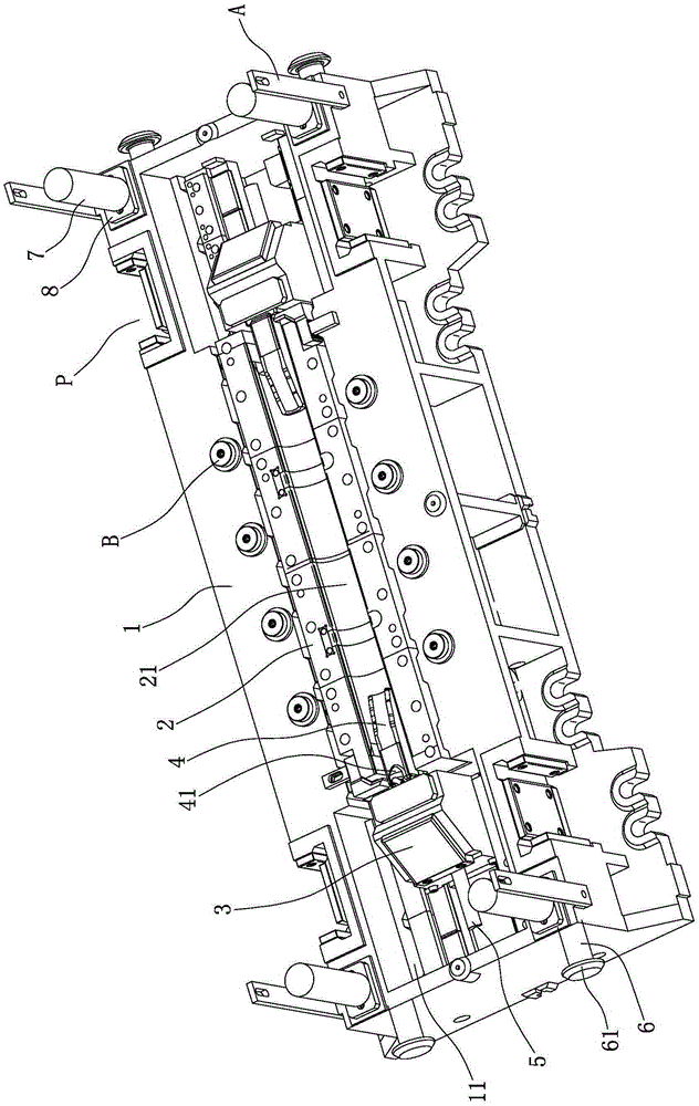
[0017] Below in conjunction with accompanying drawing and embodiment the present invention will be further described:

[0018] Such as figure 1 As shown, the mold base 1 is formed by casting. A group of lifting lugs 6 are respectively arranged on the left end surface and the right end surface of the mold base 1, and each group of lifting lugs 6 is divided into front and rear two, and four lifting lugs 6 are distributed in a rectangle on the same horizontal plane. The lifting lug 6 is a cylinder, one end of the lifting lug 6 is fixed to the mold base 1 , and the other end of the lifting lug 6 is integrally formed with an annular boss 61 . The four corners of the top surface of the mold base 1 are provided with uprights 7, the uprights 7 are cylinders, and the four uprights are distributed in a rectangle. Fixed connection.

[0019] Such as figure 1 As shown, a group of connection plates A are respectively arranged at the left and right ends of the mold base 1, and each group...


PUM


Abstract

The invention discloses a pneumatic type positioning device used for torsion beam punch forming. A tapered wedge block is arranged in each mould cavity of a mould base; opposite ends of two tapered wedge blocks are provided with mandrels; the top surface of the left mandrel is integrally formed with a convex hull which is close to the right end surface of the corresponding tapered wedge block; stand columns are arranged on four corners of the top surface of the mould base, and the lower end of each stand column is fixed with a cushion block; a group of connecting plates is arranged at each of left and right ends of the mould base; the connecting plates are in the shapes of long-strip rectangles; front and rear rows of limiting blocks are arranged on the middle part of the top surface of the mould base; the limiting blocks are two-section type hollow short columns which are small in upper parts and large in lower parts; guide slots are symmetrically formed in front and rear sides of the left end of the mould base; guide slots are also symmetrically formed in front and rear sides of the right end of the mould base; and the four guide slots are distributed in the shape of a rectangle. The pneumatic type positioning device is delicate in conception, reasonable in design, easy to implement, simple in structure and high in production efficiency; and the formed torsion beam is easy to identify in a left-right direction.

Description

technical field [0001] The invention belongs to the technical field of moulds, and in particular relates to a pneumatic positioning device for stamping and forming of torsion beams. Background technique [0002] The torsion beam is an important part of the car. Its main function is to balance the up and down jump of the left and right wheels, so as to reduce the shaking of the vehicle and keep the vehicle stable. The V-shaped torsion beam is stamped from a round tube-shaped blank. The stamping process is to form two V-shaped surfaces inside and outside at one time, and then expand the port shape twice. Chinese patent ZL201410142309.4 disclosed a car tubular V-shaped torsion beam stamping process on July 30, 2014, and specifically disclosed the forming die and the expansion die. The operation is cumbersome, the production efficiency is low, and the formed product is a left-right symmetrical piece. It is difficult to distinguish the left-right direction in the subsequent lase...

Claims


Application Information

Patent Timeline
Patent Type & Authority Applications(China)
IPC IPC(8): B21D53/88B21D37/10B21D43/00
Inventor 谭建林龚量亮张旭左勇
Owner CHONGQING SKYMAN AUTOMOBILE BODY MFG
Why Eureka
Try Eureka