Mixed combustion device and combustion equipment utilizing same

A technology of mixed combustion and combustion equipment, which is applied in the direction of combustion equipment, the combustion of block fuel and liquid fuel, and the combustion of block fuel and gaseous fuel, which can solve the problems of large energy loss and prolong the service life , easy maintenance and replacement, and optimize the effect of excess air coefficient

Inactive Publication Date: 2016-01-27
庄彦峰
View PDF19 Cites 5 Cited by
  • Summary
  • Abstract
  • Description
  • Claims
  • Application Information

AI Technical Summary

Problems solved by technology

The disadvantage of this design is that the realization of an extended function is often realized by increasing the stroke of the same flame in different combustion chambers, and the energy loss is very large. Combustion chamber switching switch for combustion switching in the mixed combustion channel, but its structure and position still need to be improved, especially to improve the position and structure of the combustion switching switch in conjunction with the optimization of the feeding port layout is very necessary to improve the efficiency of combustion equipment

Method used


Image

  • Mixed combustion device and combustion equipment utilizing same
  • Mixed combustion device and combustion equipment utilizing same
  • Mixed combustion device and combustion equipment utilizing same

Examples


Embodiment 1

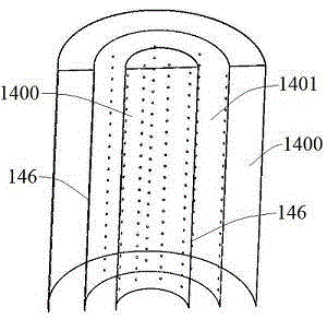
[0088] see figure 1 , a mixed combustion device of the present embodiment, the mixed combustion channel 1401 is an interlayer cavity between two medium channels 1400 to be sprayed, the mixed combustion channel 1401 is neither an air channel 142 nor a fuel channel 141, and the medium channel 1400 to be sprayed The medium to be sprayed is air and fuel, and each medium to be sprayed channel 1400 can only flow through air or fuel. The medium passage 1400 to be sprayed as the air passage 142 injects air to the mixed combustion passage 1401 through the air nozzle 1411 offered on the reaction partition wall 146; Injection port 1412 injects fuel into mixed combustion passage 1401 .

Embodiment 2

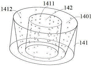
[0090] see figure 2 , a kind of mixed combustion device of the present embodiment, its center is cylindrical air passage 142, and the periphery of air passage 142 wraps truncated conical mixed combustion passage 1401, and fuel passage 141 then wraps the periphery of mixed combustion passage 1401, and fuel passage A fuel nozzle 1412 is opened on the reaction partition wall 146 between the 141 and the mixed combustion channel 1401 , and an air nozzle 1411 is opened on the reaction partition wall 146 between the air channel 142 and the mixed combustion channel 1401 .

Embodiment 3

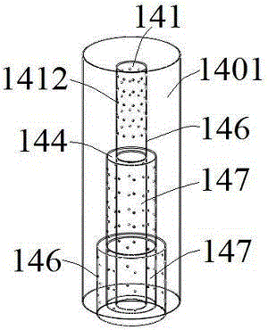
[0092] see image 3 , a mixed combustion device of the present embodiment, the center of which is a truncated conical fuel channel 141, the mixed combustion channel 1401 is an interlayer cavity between the fuel channel 141 and the air channel 142, and the reaction room between the fuel channel 141 and the mixed combustion channel 1401 A fuel nozzle 1412 is opened on the partition wall 146 , and an air nozzle 1411 is provided on the reaction partition wall 146 between the air channel 142 and the mixed combustion channel 1401 .


PUM


Abstract

The invention discloses a mixed combustion device and combustion equipment utilizing same, and belongs to the technical field of combustion equipment. The mixed combustion device comprises a to-be-sprayed medium channel and a mixed combustion channel, wherein a reaction space wall for spacing the to-be-sprayed medium and the mixed combustion channel is provided with an orifice; and a combustion medium is sprayed from the to-be-sprayed medium channel to the mixed combustion channel through the orifice. From a combustion initial end of the mixed combustion channel to a combustion exhaustion end of the mixed combustion channel, combustion conditions are optimized along with progress of a combustion process; and different matching proportions of the to-be-sprayed medium are realized according to needs of different combustion stages, mixing uniformity of different media is realized to the greatest extent to facilitate combustion. The mixed combustion device is suitable for combustion of gas fuels, can be applied to combustion of liquid and solid fuels, and is especially suitable for combustion of fuels such as natural gas, coal gas, biogas, biomass cracking fuel gas, fuel oil, methanol, pulverized coal, biomass micro powder, straws, firewood, biomass forming fuels, block-shaped coals and the like.

Description

technical field [0001] The invention relates to the technical field of combustion equipment, and more specifically, relates to a mixed combustion device and combustion equipment using the device. Background technique [0002] Energy is the basis for the survival and development of human beings. All kinds of fossil energy, biomass energy and their derivatives in the form of gas, liquid and solid are the absolutely dominant energy among the developed and utilized energy. Due to the limitations of fuel composition and combustion methods, the above-mentioned energy is prone to insufficient combustion and the production of toxic and harmful substances, which has caused great damage to the ecological environment and people's physical and mental health. For example, one of the main air pollutants emitted during the combustion process, Nitrogen oxides have been identified as degrading air quality, causing smog and acid rain. [0003] As far as fossil energy is concerned, although i...

Claims


Application Information

Patent Timeline
Patent Type & Authority Applications(China)
IPC IPC(8): F23D14/02F23D14/62F23D14/46F23C5/08
Inventor 庄彦峰
Owner 庄彦峰
Why Eureka
Try Eureka