A multi-station robot abrasive belt polishing machine with an abrasive belt drive rear

A robot abrasive belt and abrasive belt polishing technology, which is applied in the direction of grinding drive device, abrasive belt grinder, grinding/polishing equipment, etc., can solve the problems of reducing the scope of application of polishing machine equipment, reduce programming and operation difficulty, expand The scope of application and the effect of reducing the footprint of the machine

Active Publication Date: 2017-08-22
广东博科数控机械有限公司
View PDF2 Cites 0 Cited by
  • Summary
  • Abstract
  • Description
  • Claims
  • Application Information

AI Technical Summary

Problems solved by technology

However, this technical solution has the following defects in actual use, that is, the abrasive belt drive motor is located at the center of the front side of the headstock, forming a front structure for the abrasive belt drive, and the head support as a whole has a "mouth"-shaped frame structure , when the fixture robot tries to use the left and right or upper and lower head spaces to polish special-shaped or long-sized workpieces, the fixture robot will interfere with the abrasive belt drive motor, thereby limiting the shape of the polished workpiece and the length in a certain direction, which also reduces The scope of application of this structure polishing machine equipment
Another invention patent of the applicant with the publication number CN104440471A also has the defect of the abrasive belt driving front

Method used


Image

  • A multi-station robot abrasive belt polishing machine with an abrasive belt drive rear
  • A multi-station robot abrasive belt polishing machine with an abrasive belt drive rear
  • A multi-station robot abrasive belt polishing machine with an abrasive belt drive rear

Examples


Embodiment Construction

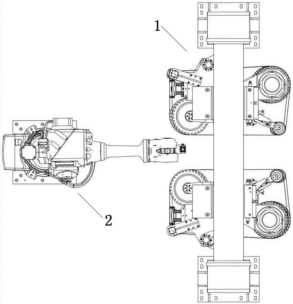
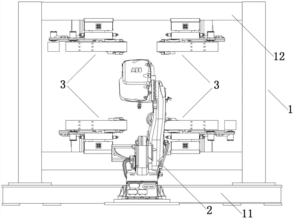
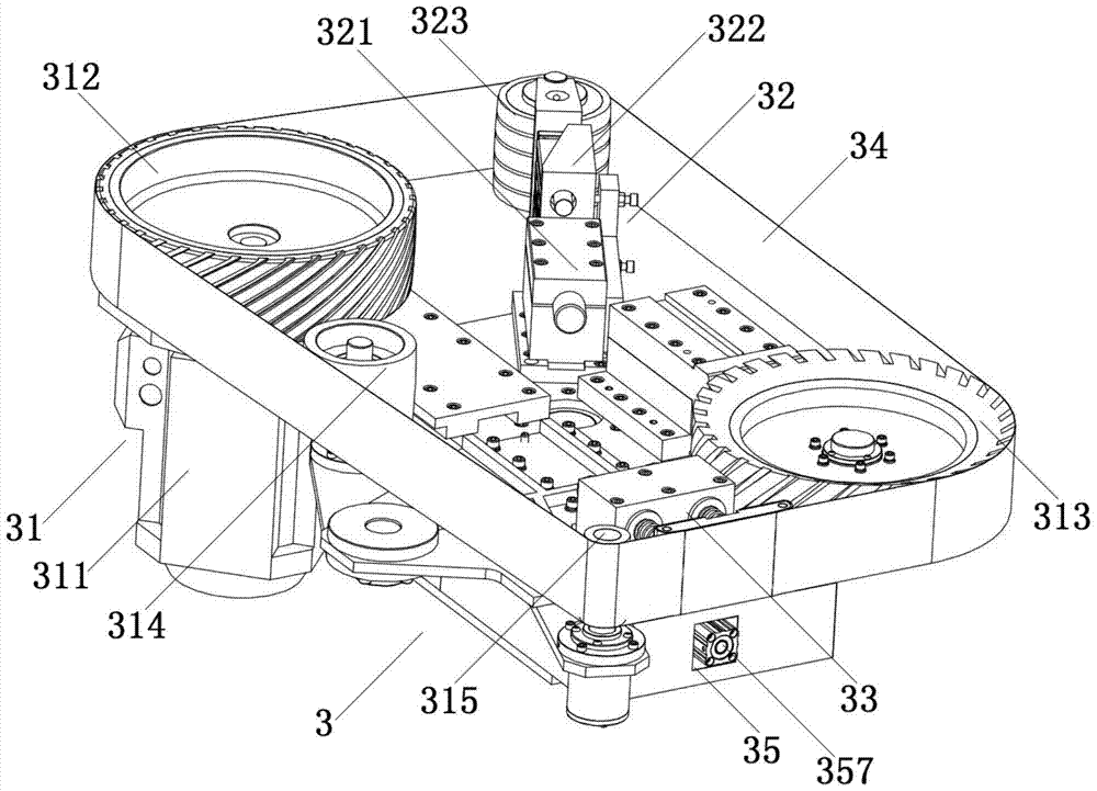
[0026] Such as Figures 1 to 5 As shown, a multi-station robot abrasive belt polishing machine with an abrasive belt drive in the present invention includes an abrasive belt polishing device 1 and a fixture robot 2 located on one side of the abrasive belt polishing device. The abrasive belt polishing device 1 includes an organic base 11, a head support frame 12 arranged on the base, and four polishing heads 3 arranged on the head support frame, wherein: the main part of the head support frame 12 is in the shape of a "mouth" Frame structure, the upper beam and the lower beam of the frame structure are respectively symmetrically provided with two polishing heads, and the above four polishing heads 3 also form a "mouth"-shaped arrangement structure; each polishing head 3 is provided with a hollow structure The headstock 36, the front side of the headstock 36 is provided with an abrasive belt drive assembly 31, an abrasive belt tensioning assembly 32, a spring liner assembly 33 an...


PUM


Abstract

The invention discloses a multi-station robot belt sander with rear-arranged abrasive belt drive. The multi-station robot belt sander comprises an abrasive belt polishing device and a clamp robot. The abrasive belt polishing device comprises a base, a machine head supporting frame arranged on the base and two or more sander heads arranged on the machine head supporting frame, and each sander head comprises an abrasive belt drive assembly, an abrasive belt tensioning assembly and a sander head swinging assembly. In each abrasive belt drive assembly, the rear-arranged abrasive belt drive structure that an abrasive belt drive motor is arranged in the rear and a power output shaft of the motor is directly connected to an abrasive belt driving wheel in a fastened mode is adopted. According to the multi-station robot belt sander, the rear-arranged abrasive belt drive structure form is adopted, the clamp robot does not interfere with the abrasive belt drive motors when trying to polish special-shaped work-pieces or long work-pieces between the sander heads on the left and on the right or the sander heads at the upper part and at the lower part, available sanding areas of abrasive belts can be maximized, the structure adapts to shape change of work-pieces to be polished and length increase in a certain direction, and the application range of the multi-station robot belt sander of the structure is extended.

Description

technical field [0001] The invention relates to an abrasive belt polishing machine, which belongs to the technical field of numerical control polishing equipment, in particular to a multi-station robot abrasive belt polishing machine with an abrasive belt drive behind. Background technique [0002] The traditional polishing work is generally done manually, that is, the operator holds the workpiece close to the polishing machine for polishing. This method is labor-intensive, low in efficiency, and the operator is easily polluted by dust. Therefore, a robotic abrasive belt polishing machine that uses robots instead of manual labor came into being. This type of polishing machine better solves the problems of complex line shape and multi-variety parts surface grinding and reduces the labor intensity of the operator and dust pollution. [0003] At present, in the technical solution disclosed by the applicant in 2014 with the publication number CN104440470A and the invention paten...

Claims


Application Information

Patent Timeline
Patent Type & Authority Patents(China)
IPC IPC(8): B24B21/00B24B21/20B24B47/16B24B47/14B24B41/06B24B41/02B24B41/00B24B55/08
CPCB24B21/008B24B21/20B24B41/005B24B41/02B24B41/06B24B47/14B24B47/16B24B55/08
Inventor 梁志强
Owner 广东博科数控机械有限公司
Why Eureka
Try Eureka