
Curved surface mirror image grinding system

A grinding and mirroring technology, which is used in metal processing equipment, grinding machine parts, grinding/polishing equipment, etc., can solve the problem of difficulty in ensuring the stability of blade grinding surface quality, harsh operating environment for manual grinding of wind power blades, etc. The problem of high labor intensity of grinding workers can improve the service life and grinding quality, eliminate occupational hazards, and reduce labor intensity.

Active Publication Date: 2016-01-20
UNIV OF ELECTRONICS SCI & TECH OF CHINA
View PDF5 Cites 17 Cited by
  • Summary
  • Abstract
  • Description
  • Claims
  • Application Information

AI Technical Summary

Problems solved by technology

[0004] 1. The overall grinding area of ​​a single blade of a megawatt-scale wind power blade is at least 150 square meters, resulting in extremely labor-intensive grinding workers, low production efficiency, and it is difficult to ensure the stability of the blade grinding surface quality;
[0005] 2. The operating environment of manually grinding wind power blades is extremely harsh. Long-term work is likely to cause occupational diseases such as silicosis to the grinding workers. In addition, the grinding dust contains harmful chemical components such as amine curing agents and styrene thinners used to prepare shaped blades. Exposed skin Long-term exposure to these harmful ingredients will cause infertility and cancer in workers

Method used


Image

  • Curved surface mirror image grinding system
  • Curved surface mirror image grinding system
  • Curved surface mirror image grinding system

Examples


Embodiment Construction

[0029] The present invention will be further described below in conjunction with accompanying drawing. Embodiments of the present invention include, but are not limited to, the following examples.

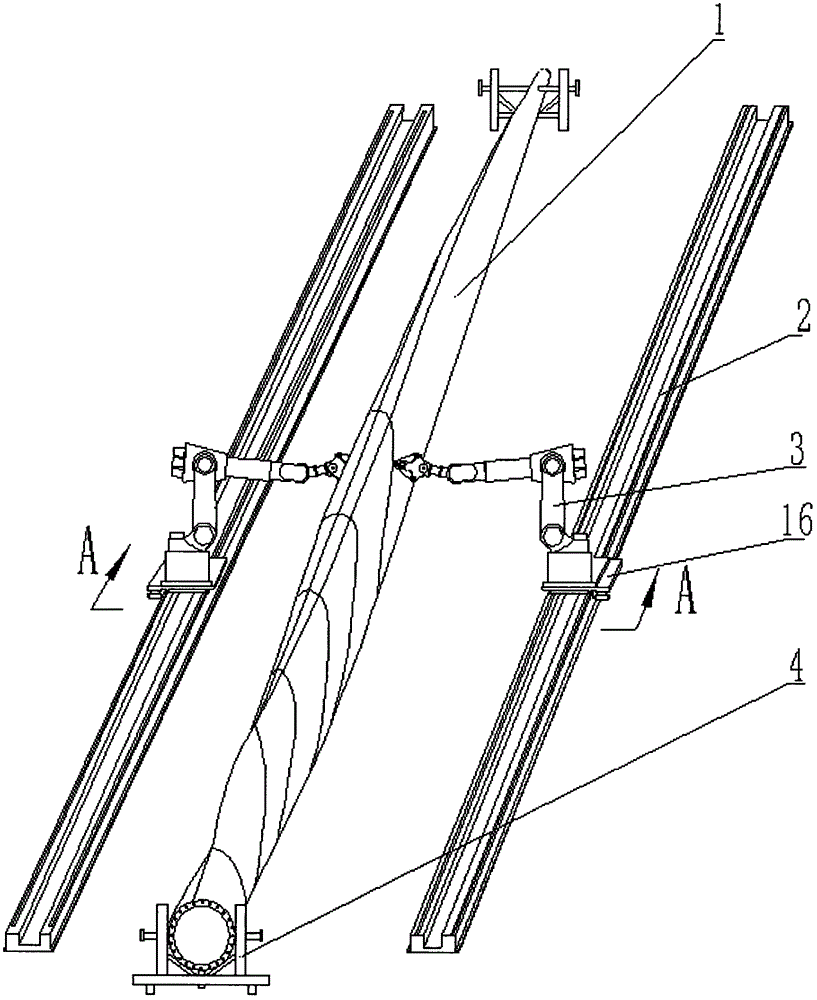
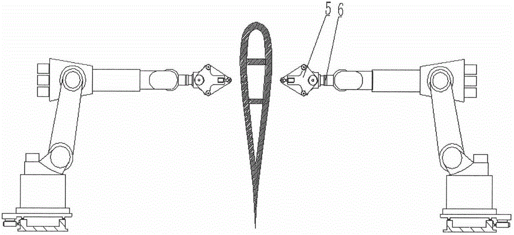
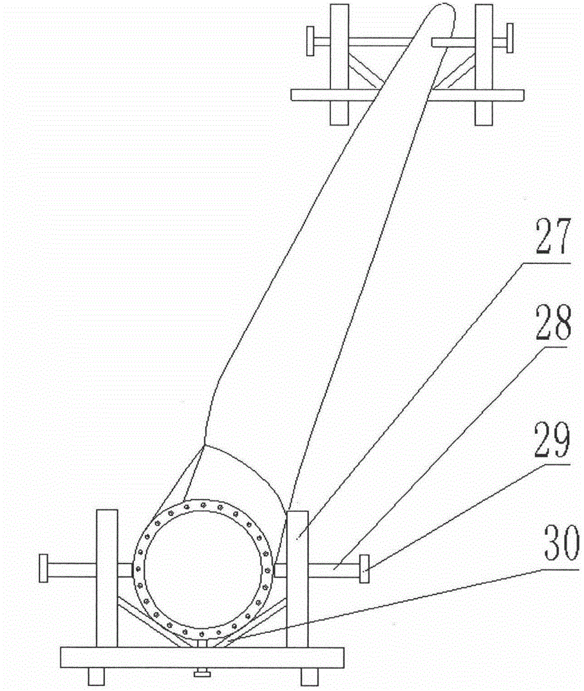
[0030] Such as figure 1 , figure 2 As shown, it is an overall structural axonometric view and A-A sectional view of a preferred example of the curved surface mirror grinding processing system of the present invention. It includes a six-axis industrial robot (3) and a sliding table device (16) symmetrically arranged in parallel on both sides of the axis of the wind power blade workpiece (19), and the large wind power blade curved surface workpiece (1) to be polished is placed on the support (4), six The axis industrial robot is installed and fixed on the slide plate (19), and is arranged on the flange (6) of the end joint of the six-axis industrial robot. The grinding head motor (13) on the top drives the abrasive belt (10) to rotate at a high speed, and the sliding table device...


PUM


Abstract

The invention discloses a curved surface mirror image grinding system. The problems of excessively low efficiency, poor surface qualities, high labor intensity, severe dust harm and the like during manual grinding of wing-type curved surfaces of existing large wind power vanes are mainly solved. The curved surface mirror image grinding system comprises six-axis industrial robots, supports, sliding table devices and grinding devices; the industrial robots integrated with the grinding devices are arranged in dual directions in a mirror symmetry mode with the axis of a wind power vane workpiece as the center line and cooperate to carry out parallel control over the grinding devices to perform mirror symmetry grinding motions with different poses in working space, and dual-direction automatic mirror image grinding and polishing of the wind power vane curved surfaces can be achieved. The curved surface mirror image grinding system is ingenious in structural design; the grinding and polishing efficiency of the wind power vane curved surfaces is high; the ground and polished surface qualities are good; the production cost of the wind power vanes is greatly reduced; potential harm of grinding dust to people is eliminated; the good practical and popularizing value is achieved.

Description

technical field [0001] The invention belongs to the technical field of wind power generation equipment manufacturing, and relates to the grinding and polishing processing of megawatt-level large-scale wind power blade profile surfaces, specifically, an automatic high-efficiency grinding processing system for complex curved surfaces of large-scale wind power blade airfoil surfaces . Background technique [0002] As an important core part of wind power generation equipment, wind power blades account for 15-20% of the cost of the whole machine. The airfoil surface is a complex aerodynamic curved surface. The manufacturing accuracy and surface quality of the curved surface will directly affect the wind energy conversion efficiency and blade use. Life and fan safety. Megawatt-level wind power blades are generally made by placing composite material preforms such as glass fiber in the mold cavity, injecting resin, heating and pressurizing molding technology, which is affected by m...

Claims


Application Information

Patent Timeline
IPC IPC(8): B24B21/16B24B21/18B24B41/04B24B55/08
Inventor 黄智陈令万从保周振武
Owner UNIV OF ELECTRONICS SCI & TECH OF CHINA
Learn More