Roller cleaning mechanism of template cleaning machine

The technology of a cleaning mechanism and cleaning machine is applied in cleaning methods and utensils, cleaning methods using tools, cleaning methods using liquids, etc., which can solve problems such as primitive operation methods, low efficiency, and harsh working environments, and achieve easy installation and Maintenance, saving power output, good running performance

Inactive Publication Date: 2016-01-20
ZHUO DA NEW MATERIAL TECH GRP
View PDF5 Cites 8 Cited by
  • Summary
  • Abstract
  • Description
  • Claims
  • Application Information

AI Technical Summary

Problems solved by technology

In building material enterprises, the cleaning of the formwork used in production is a cumbersome, inefficient, and labor-intensive necessary process. At present, most of the industrial production processes use manual cleaning, with primitive operation methods, harsh working environments, and low efficiency. And the expected effect is not achieved, the safety factor of workers is low, it is not suitable for the production of large-scale automatic production lines, not only the cleaning effect is poor, but also the template is easy to be damaged, and the quality is difficult to control
Stencil cleaning machine can be used to clean the stencil. Stencil cleaning is a very important process. Due to the limitation of the production capacity of the plate production line, it is necessary to complete the cleaning process with very high efficiency and fast speed. The roller cleaning mechanism of the stencil cleaning machine It is a very critical device, but the existing roller cleaning mechanism generally has the problems of unstable operation and low efficiency. Therefore, a new roller cleaning mechanism of the template cleaning machine is needed

Method used


Image

  • Roller cleaning mechanism of template cleaning machine
  • Roller cleaning mechanism of template cleaning machine
  • Roller cleaning mechanism of template cleaning machine

Examples


Embodiment Construction

[0022] The technical solutions in the embodiments of the present invention will be clearly and completely described below in conjunction with the accompanying drawings in the embodiments of the present invention. Obviously, the described embodiments are only some, not all, embodiments of the present invention. Based on the embodiments of the present invention, all other embodiments obtained by persons of ordinary skill in the art without creative efforts fall within the protection scope of the present invention.

[0023] For the convenience of description below, the "left", "right", "upper" and "lower" referred to below are consistent with the left, right, upper and lower directions of the drawings themselves. "Front end", "rear end" or "end" etc. refer to the left and right of the drawing itself. "First", "second" and so on are used to distinguish each other in description, and have no other special meanings.

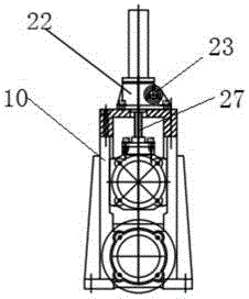
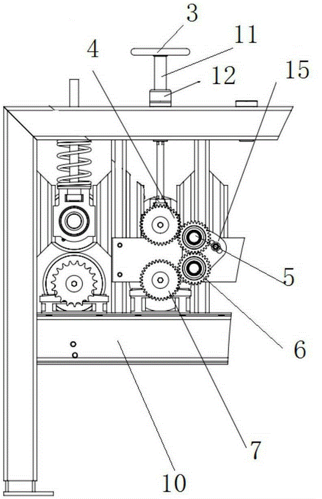
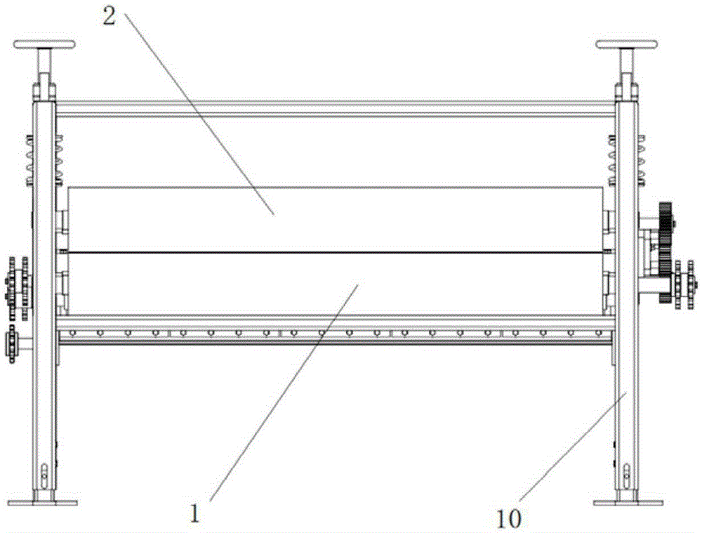
[0024] Such as Figures 1 to 6 As shown, the present invention ...


PUM


Abstract

The invention discloses a roller cleaning mechanism of a template cleaning machine. An upper cleaning roller and a lower cleaning roller are installed on a bracket and each comprise a brush roller and a scraper roller. The upper cleaning roller and an upper roll shaft gear are arranged coaxially, and the upper roll shaft gear is installed at the end of the upper cleaning roller. The lower cleaning roller and a lower roll shaft gear are arranged coaxially, and the lower roll shaft gear is installed at the end of the lower cleaning roller. A driving device drives the upper cleaning roller or the lower cleaning roller to rotate, and the upper roll shaft gear and the lower roll shaft gear are in an engaged driving mode through an idle pulley mechanism. The roller cleaning mechanism of the template cleaning machine is provided with the gear driving system, thereby being high in driving efficiency and realizing the purpose of cleaning templates efficiently; the interval between the upper cleaning roller and the lower cleaning roller can be adjusted in time as needed, so that demands of assembly line production are met, and the productivity can be improved. Meanwhile, the roller cleaning mechanism is easy to install and maintain, saves power output and has quite good practicability.

Description

technical field [0001] The invention relates to the technical field of building plate processing equipment, in particular to a roller cleaning mechanism of a template cleaning machine. Background technique [0002] Composite panels are very widely used building materials at present. The production of composite panels generally needs to go through pressing molding - adding glass fiber cloth - adding non-woven fabric - cutting - curing molding - demoulding and other processes. In the production process, the composite board can be processed and produced on the automatic production line. After the production is completed, the composite board will be separated from the mold or formwork, but it is inevitable that the composite board slag and other sundries will remain on the formwork. In building material enterprises, the cleaning of the formwork used in production is a cumbersome, inefficient, and labor-intensive necessary process. At present, most of the industrial production pr...

Claims


Application Information

Patent Timeline
Patent Type & Authority Applications(China)
IPC IPC(8): B29C33/72B08B1/02B08B3/02
Inventor 杨卓舒牛彦强周其王丰王敬涛
Owner ZHUO DA NEW MATERIAL TECH GRP
Why Eureka
Try Eureka