A gas conveying biomass feeder
A biomass and feeder technology, applied in the direction of educts, granular/powder fuel gasification, reagents, etc., can solve the problems that the biomass feeder cannot operate normally, the feeding is not easy, the angle of repose is large, etc. Achieve the effect of low basic investment cost and maintenance cost, wide application range, and reduced adhesion
- Summary
- Abstract
- Description
- Claims
- Application Information
AI Technical Summary
Problems solved by technology
Method used
Image

Examples
Embodiment 1
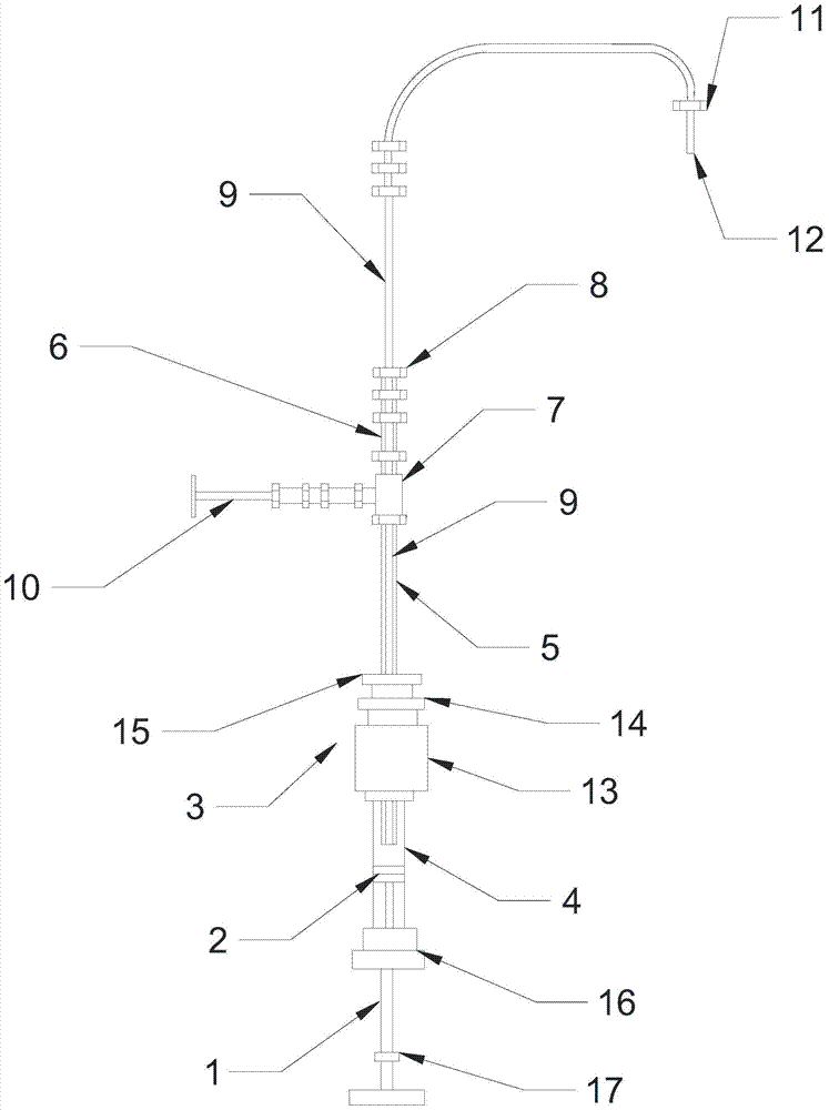
[0023] Such as figure 1 and figure 2 As shown, a gas delivery biomass feeder of the present invention includes an air supply pipe 10, an air inlet pipe, a feed pipe 9 and a storage pipe 4 for containing biomass materials; the air supply pipe 10 and the air inlet pipe Fixed connection and gas conduction, the inlet pipe is sleeved on the feed pipe 9, and the feed port of the feed pipe 9 is arranged in the tube hole at the second end of the storage pipe 4, and the storage A sealing plug 2 that can move axially along the storage tube 4 is provided in the tube hole at the first end of the tube 4, and the first end of the sealing plug 2 is fixedly connected with the push rod 1; the first end of the storage tube 4 The two ends are sealed and connected with the outer wall of the air intake pipe through the first variable diameter joint 3; the first end of the air intake pipe is arranged in the storage pipe 4, and the second end of the air intake pipe passes through the second variab...
Embodiment 2
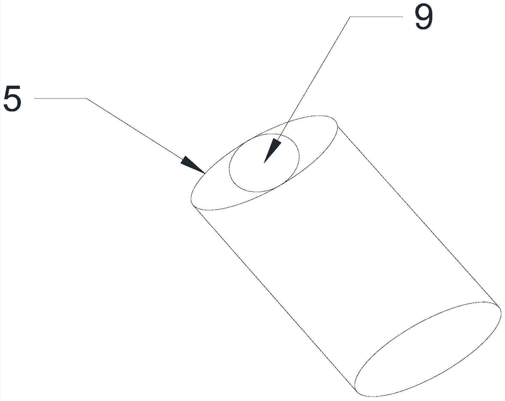
[0031] The difference between this embodiment and Embodiment 1 is that the feed port of the feed pipe 9 is flush with the gas outlet of the air intake pipe, and the feed port of the feed pipe 9 is flush with the gas outlet of the air intake pipe. The air outlet is above the biomass material and is 2 to 3 mm away from the horizontal surface of the biomass material, the inner diameter of the first air inlet pipe 5 and the second air inlet pipe 6 is 4 mm, and the outer diameter of the feed pipe 9 is 3 mm, that is The difference between the inner diameter of the inlet pipe and the outer diameter of the feed pipe 9 is less than 3 mm. In this case, the use of the present invention to transport biomass materials to the gasifier can also achieve the effect of stable feeding. Minute feed 0.500 grams calculation, the error is only ± 0.015 grams.
Embodiment 3
[0032] Embodiment 3 (comparative example)
[0033] The difference between this embodiment and Embodiment 1 is that the inner diameter of the first air inlet pipe 5 and the second air inlet pipe 6 is 8 mm, and the outer diameter of the feed pipe 9 is 4 mm. At this time, the air inlet pipe The difference between the inner diameter of the feed pipe 9 and the outer diameter of the feed pipe 9 is greater than 3 mm. Through the air supply pipe 10 to ventilate into the air inlet pipe, no matter how much the gas flow rate is and how much the distance between the inlet of the feed pipe 9 and the gas outlet of the air inlet pipe and the horizontal plane of the biomass material is, it cannot be realized. Feeding: the air flow flows into the material storage pipe through the air inlet pipe and blows on the surface of the material, and then forms a reverse air flow, which drives the material to flow to the feed inlet of the feed pipe 9, but due to the air inlet pipe and the feed material ...
PUM
 Abstract
Description
Claims
Application Information
 - R&D
- Intellectual Property
- Life Sciences
- Materials
- Tech Scout
- Unparalleled Data Quality
- Higher Quality Content
- 60% Fewer Hallucinations
Browse by: Latest US Patents, China's latest patents, Technical Efficacy Thesaurus, Application Domain, Technology Topic, Popular Technical Reports.
© 2025 PatSnap. All rights reserved.Legal|Privacy policy|Modern Slavery Act Transparency Statement|Sitemap|About US| Contact US: help@patsnap.com