Ultrasonic metering ball valve

An ultrasonic and ball valve technology, applied in the field of ultrasonic metering ball valves, achieves the effects of high measurement accuracy, long service life and simple structure

Active Publication Date: 2016-01-20
武汉卓瑞芯科技有限公司
View PDF7 Cites 3 Cited by
  • Summary
  • Abstract
  • Description
  • Claims
  • Application Information

AI Technical Summary

Problems solved by technology

[0005] The purpose of the present invention is to overcome the problem that most of the existing ball valves are only used to cut off, cut off and change the flow direction of the fluid in the fluid pipeline, and most of the valves and flow meters in the pipeline are installed separately. Ultrasonic metering ball valve has the characteristics of not only being able to control fluid on-off, but also measuring fluid flow without being affected by fluid quality, high measurement accuracy, long service life, simple structure, and convenient installation and maintenance.

Method used


Image

  • Ultrasonic metering ball valve
  • Ultrasonic metering ball valve

Examples


Embodiment 1

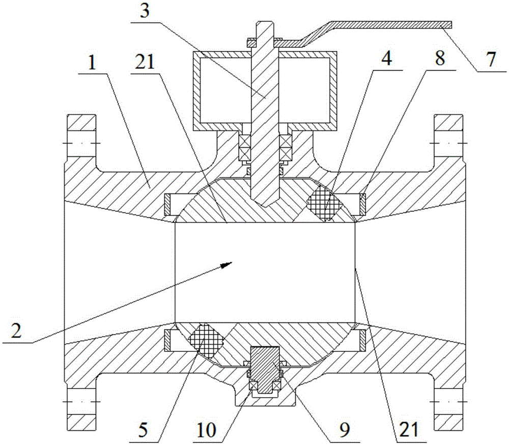
[0027] Such as figure 1 The ultrasonic metering ball valve shown includes a valve body 1, a ball core 2 disposed in the valve body 1, and a valve stem 3 that drives the ball core 2 to rotate; the ball core 2 is provided with a fluid through hole 21, and the inner wall of the fluid through hole 21 There is an ultrasonic sensor for measuring fluid flow. The ultrasonic sensor includes a pair of sending sensors 4 and receiving sensors 5 , and the sending sensors 4 and receiving sensors 5 are symmetrically arranged around the center point of the fluid through hole 21 .

[0028] The upper end of the valve stem 3 is provided with a drive motor (not shown) or a handle 7 for driving the valve stem 3 to rotate. It also includes a control part (not shown in the figure) and a power supply part (not shown in the figure); the control part includes a single-chip microcomputer (not shown in the figure) and a drive motor control module (not shown in the figure); the standard flow data entered...

Embodiment 2

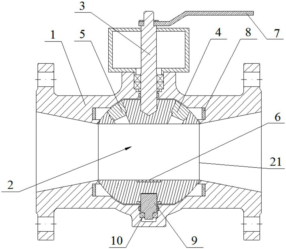
[0031] Such as figure 2 As shown, the structure of the ultrasonic metering ball valve in this embodiment is basically the same as in Embodiment 1, the difference is that the ultrasonic sensor includes a group of sending sensors 4, receiving sensors 5 and reflective sheets 6, and the ultrasonic waves emitted by the sending sensors 4 are reflected by the reflective sheets 6 To the receiving sensor 5; the transmitting sensor 4 and the receiving sensor 5 are arranged mirror-symmetrically with the axial section of the fluid through hole 21 or the section perpendicular to the axis, and the reflective sheet 6 is arranged between the transmitting sensor 4 and the receiving sensor 5 and the reflective sheet 6 The reflective surface is opposite to the transmitting end of the transmitting sensor 4 and the receiving end of the receiving sensor 5 . The included angle between the extended line of the midline of the sending sensor 4 and the vertical line of the reflective sheet 6 is equal t...


PUM


Abstract

The invention discloses an ultrasonic metering ball valve which comprises a valve body, a ball core arranged in the valve body and a valve rod driving the ball core to rotate. A fluid through hole is formed in the ball core, and ultrasonic sensors used for measuring the flow of fluid are arranged on the inner wall of the fluid through hole. The ultrasonic sensors comprise the paired sending sensor and receiving sensor. The sending sensor and the receiving sensor are in central symmetry with the fluid through hole as the center. The ultrasonic metering ball valve has the beneficial effects that the ultrasonic sensors are used for measuring the flow of the fluid, the measuring precision is not affected by the fluid, no other obstacles exist in the fluid through hole, the measuring precision is high, the structure is simple, installation is convenient, the service life is long, the problem that a valve and a flow meter are separately installed in a pipeline is solved, and cost is reduced.

Description

technical field [0001] The invention relates to the technical field of valves and fluid metering, in particular to an ultrasonic metering ball valve. Background technique [0002] The ball valve is not only simple in structure and good in sealing performance, but also has the advantages of small size, light weight, less material consumption, small installation size, small driving torque, easy operation, and easy quick opening and closing within a certain nominal size range. One of the fastest growing valve varieties in the past ten years. [0003] The use of ball valves is very extensive, and the variety and quantity of use are still expanding, and they are developing in the direction of high temperature, high pressure, large diameter, high sealing, long life, excellent adjustment performance, and one valve with multiple functions. Its functional diversity has become an important indicator to show the technical level of the national valve industry, and it is also an importa...

Claims


Application Information

Patent Timeline
Patent Type & Authority Applications(China)
IPC IPC(8): F16K5/06F16K5/08F16K37/00F16K31/04
CPCF16K5/06F16K5/0647F16K5/0689F16K31/042F16K37/0091
Inventor 黄忠李进武陆勇喜
Owner 武汉卓瑞芯科技有限公司
Why Eureka
Try Eureka