Eureka AIR delivers breakthrough ideas for toughest innovation challenges, trusted by R&D personnel around the world.

Reverse recoil brake design method

A brake and anti-recoil technology, which is applied in the direction of the muzzle attachment, etc., can solve the problems of no use value for moving point targets, limited braking ability, and poor performance of the brake, so as to achieve a natural balance and shorten the overall The effect of gun length and lowering the height of the line of fire

Inactive Publication Date: 2016-01-20
黄渊干
View PDF4 Cites 0 Cited by
  • Summary
  • Abstract
  • Description
  • Claims
  • Application Information

AI Technical Summary

Problems solved by technology

Due to the poor performance of the existing brakes, many important military equipment have given up the use of , and the breech fire-breathing rockets can only use rockets with a very low muzzle velocity and high cost, and the accuracy is very poor. It can strike fixed surface targets, but has no use value against moving point targets
[0003] Most of the existing muzzle brakes do not have an automatic shutter, so they cannot actively control the pressure distribution of the gun. The horizontal outlets on the side of the muzzle brake are designed to be large and the result is half the effort, because most of the high-temperature and high-pressure airflow has no time to expand. Expelled through the mouth, it will inevitably form a strong recoil force, which is the result of the law of inertia
The seatless brake developed by me is equipped with an automatic shutter, which has strong active control ability, but the automatic shutter of the brake needs to quickly tap the rear outlet of the piston under high temperature and high pressure conditions. Its structure does not have a reinforced design, and it is easy to deform, causing frequent failures, limited retreat ability and difficult maintenance, so this product can only be used for slow-fire guns and has a high cost of use
[0004] Conventional guns with high chamber pressure have high precision and low cost. They have good strike effects on fixed targets, moving targets, point targets, and surface targets. The disadvantage is that they have a lot of recoil

Method used


Image

  • Reverse recoil brake design method
  • Reverse recoil brake design method
  • Reverse recoil brake design method

Examples


Embodiment Construction

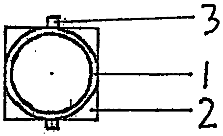
[0010] exist figure 1 Middle: 1 is the interface barrel, 2 is the interface plate, and 3 is the reinforcement plate.

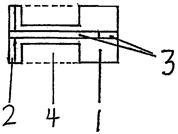
[0011] exist figure 2 Middle: 1 is the interface barrel, 2 is the interface plate, 3 is the reinforcement plate, and 4 is the horizontal outlet. According to the difference of the rate of fire of the matching guns, the length of the horizontal outlet can be adjusted to 1-3 times of the caliber of the gun (the matching drawing in this book is set as 1 time), so the interface tube and its supporting reinforcement plate, the horizontal outlet tube and the The connecting rod should also be lengthened accordingly.

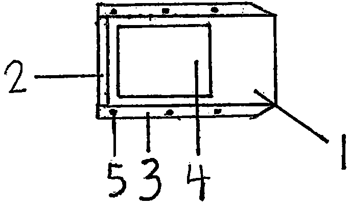
[0012] exist image 3 Middle: 1 is the interface barrel, 2 is the interface plate, 3 is the reinforcement plate, 4 is the horizontal outlet, and 5 is the screw socket.

[0013] exist Figure 4 Middle: 6 is the outlet tube, 7 is the foot.

[0014] exist Figure 5 Middle: 4 is the horizontal outlet, 5 is the screw socket, 6 is the outlet cylinder,...


PUM


Abstract

The invention discloses a reverse recoil brake design method, belongs to the field of design of guns, and can solve the recoil problem of the guns. The reverse recoil brake design method is characterized by using an automatic shutter mounted in a shutter box for automatically controlling a moving direction of high-pressure air, so that the high-pressure air is exhausted from transverse outlet cylinders at two sides of a joint cylinder to convert the non-control distribution of pressure of the guns to the control distribution. The reverse recoil brake design method has main purposes of thoroughly eliminating the recoil force of the guns and quickly stopping the recoil motion of the guns.

Description

(1) Technical field [0001] Gun design. (2) Background technology [0002] The function of the gun brake is to reduce the recoil of the gun, and its highest standard is to completely eliminate the recoil. Due to the poor performance of the existing brakes, many important military equipment have given up the use of <such as tanks>, and the breech fire-breathing rockets can only use rockets with a very low muzzle velocity and high cost, and the accuracy is very poor. It can strike fixed surface targets, but has no use value against moving point targets. [0003] Most of the existing muzzle brakes do not have an automatic shutter, so they cannot actively control the pressure distribution of the gun. The horizontal outlets on the side of the muzzle brake are designed to be large and the result is half the effort, because most of the high-temperature and high-pressure airflow has no time to expand. Expelled from the mouth, it will inevitably form a strong recoil force, whi...

Claims


Application Information

Patent Timeline
IPC IPC(8): F41A21/36
Inventor 黄渊乾
Owner 黄渊干
Why Eureka
Eureka Blog
Learn More