Blade dynamic frequency test apparatus using magnetic excitation

A technology of dynamic frequency and testing equipment, which is applied in vibration testing, measuring equipment, testing of machine/structural components, etc., can solve problems such as overheating of testing equipment, temperature rise, nitrogen pressure loss, etc., to improve equipment safety, Switching control is simple and the effect of increasing service time

Active Publication Date: 2016-01-20
XIAN THERMAL POWER RES INST CO LTD
View PDF5 Cites 8 Cited by
  • Summary
  • Abstract
  • Description
  • Claims
  • Application Information

AI Technical Summary

Problems solved by technology

[0004] With the continuous development of turbomachinery in the direction of high power and high efficiency, the length of blades continues to increase, the power of single-stage blades continues to increase, and the requirements for blade dynamic frequency testing technology continue to increase. , affecting the vacuum degree of the test environment, and with the continuous increase of the exciting air flow, the blades do work on the air flow, which makes the temperature rise, causing unfavorable factors such as overheating of the test equipment
[0005] At present, the blade dynamic frequency test system uses the method of nitrogen injection excitation, which has the following problems: 1. Nitrogen excitation will affect the vacuum degree in the test vacuum cylinder; 2. It will cause the temperature in the test cylinder to rise; 3. Each test needs to reserve nitrogen in advance, which is costly; 4. The pressure of nitrogen is lost, and the excitation force is reduced; 5. It is inconvenient to manually switch the valve of the nitrogen tank many times during the test

Method used


Image

  • Blade dynamic frequency test apparatus using magnetic excitation
  • Blade dynamic frequency test apparatus using magnetic excitation
  • Blade dynamic frequency test apparatus using magnetic excitation

Examples


Embodiment Construction

[0039] The present invention will be described in further detail below in conjunction with the accompanying drawings.

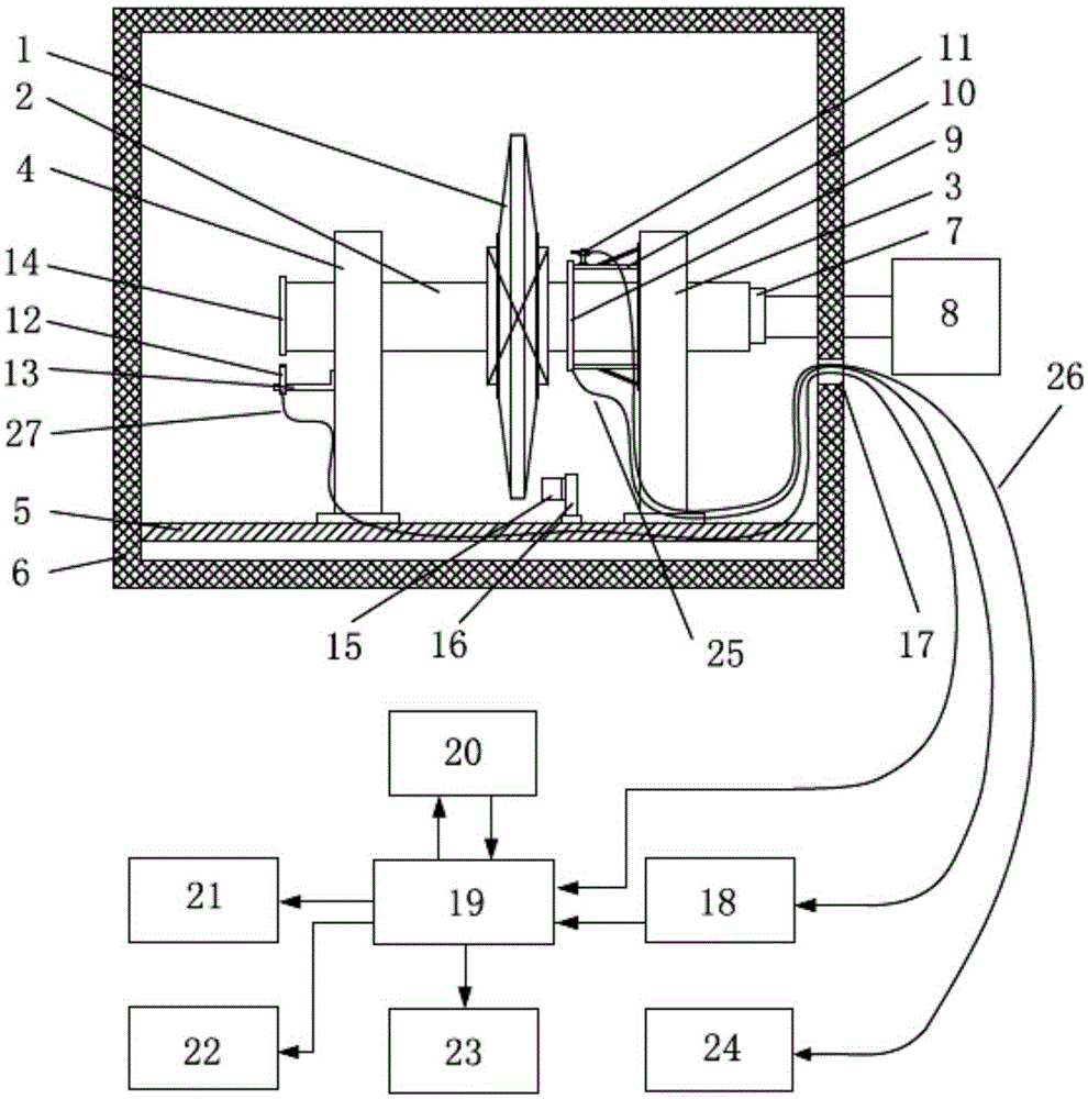
[0040] see figure 1 , the present invention is a blade dynamic frequency test device using magnetic excitation, including a vacuum cylinder 6, and a front swing frame 3 and a rear swing frame 4 installed in the vacuum cylinder 6, the impeller 1 to be tested together with the rotating shaft 2 Installed on the front swing frame 3 and the rear swing frame 4, and fixed on the swing frame track 5 inside the vacuum cylinder 6, the front section of the rotating shaft 2 is connected with the output shaft of the drive motor 8 outside the vacuum cylinder 6 with a coupling 7 .

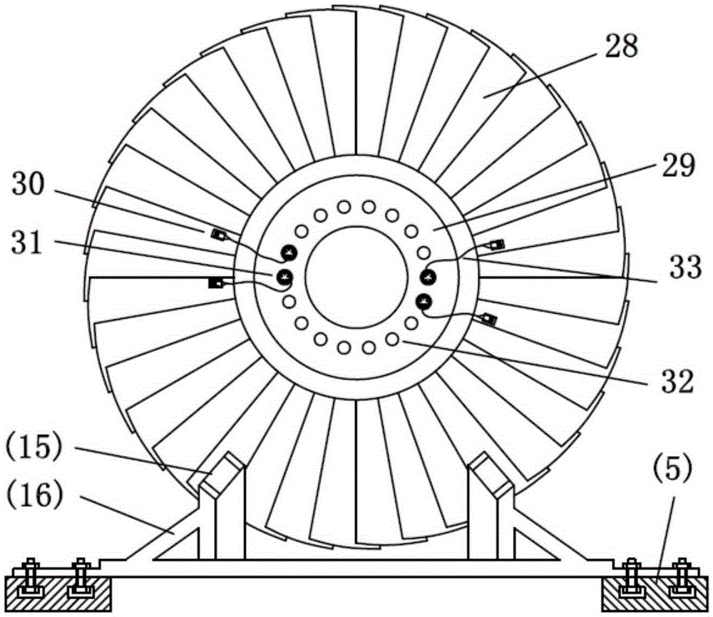
[0041] One or more magnetic exciters 15 can be selected to be arranged along the circumference of the impeller 1 , and the magnetic exciter bracket 16 is fixed on the rail 5 of the swing frame in the vacuum cylinder 6 . The receiving antenna 9 is fixed on the front swing frame 3 together with th...


PUM


Abstract

Disclosed is a blade dynamic frequency test apparatus using magnetic excitation. A magnetic exciter is used for applying an excitation force to a rotating blade, a strain gage is used for sensing blade vibration information, a signal transmitter transmits the blade vibration information sensed by the strain gage in real time via radio, and a signal receiver receives the collected blade vibration information in real time via a receiving antenna and transmits the blade vibration information to a multi-channel controller. Multiple input and output channels of a magnetic tape recorder are connected with the multi-channel signal controller and used for storing the blade vibration information of each channel. The multi-channel signal controller selects one- or multi-channel signals for a data analyzer for analyzing blade vibration characteristics. A thermometer, a tachometer and an oscilloscope are used for monitoring the temperature near the signal transmitter, the rotor velocity and signals of different channels in real time respectively. The invention solves the problem that a blade vibration frequency test using gas excitation would cause over temperature of equipment, and the invention is simple in structure, high in safety, low in cost, pollution-free, and capable of meeting blade vibration frequency test requirements.

Description

Technical field: [0001] The invention relates to a blade dynamic frequency testing device, in particular to a blade dynamic frequency testing device using magnetic force excitation. Background technique: [0002] Blade dynamic frequency test technology provides important test data basis for the design of turbomachinery blades such as steam turbines and gas turbines, and is one of the key technologies in the field of blade design and test technology. With the development of blade vibration and structural strength design technology and the continuous deepening of blade vibration safety research, higher requirements are put forward for the safety, reliability and accuracy of the blade dynamic frequency test system. [0003] The core of the blade dynamic frequency test method is to use radio signal transmission technology to install a signal transmitter on the rotating blisk, convert the blade vibration information sensed by the strain gauge into an electrical signal and transmi...

Claims


Application Information

Patent Timeline
Patent Type & Authority Applications(China)
IPC IPC(8): G01M7/02
Inventor 上官博肖俊峰高松于飞龙张永宁李园园南晴段静瑶
Owner XIAN THERMAL POWER RES INST CO LTD
Why Eureka
Try Eureka