
Time synchronization method, programmable logic device, single board and network element

A technology of programming logic and time synchronization, applied in the field of communication, can solve problems such as insufficient ability to send packets

Active Publication Date: 2016-01-20
ZTE CORP
View PDF8 Cites 12 Cited by
  • Summary
  • Abstract
  • Description
  • Claims
  • Application Information

AI Technical Summary

Problems solved by technology

[0004] The present invention provides a time synchronization method, a programmable logic device, a single board and a network element, which solves the problem that due to the special limitation of the CPU architecture in the existing method, the time synchronization response must be completed through software interrupts, resulting in insufficient packet sending capability The problem

Method used


Image

  • Time synchronization method, programmable logic device, single board and network element
  • Time synchronization method, programmable logic device, single board and network element
  • Time synchronization method, programmable logic device, single board and network element

Examples


Embodiment 1

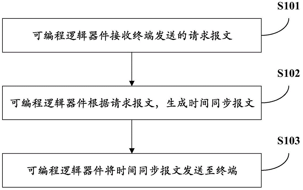
[0088] Such as figure 1 A flow chart of the time synchronization method provided by Embodiment 1 of the present invention, such as figure 1 As shown, the time synchronization method includes:

[0089] S101: the programmable logic device receives the request message sent by the terminal;

[0090] Specifically, the terminal communicates and interacts with the CPU or the programmable logic device in real time, so as to complete corresponding functions.

[0091] When the terminal needs to perform link establishment communication, the terminal generates a link establishment request message and sends the link establishment request message to the programmable logic device. Since the programmable logic device can communicate and interact with the terminal in real time, the programmable logic device By parsing all the received messages, the link establishment request message sent by the terminal can be received and identified.

[0092] When the terminal needs to perform time synchro...

Embodiment 2

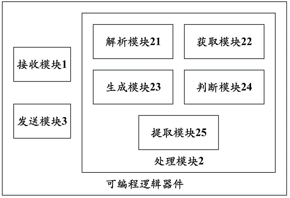
[0112] Such as figure 2 A schematic structural diagram of a programmable logic device provided in Embodiment 2 of the present invention, such as figure 2 As shown, the programmable logic device includes:

[0113] The receiving module 1 is configured to receive the request message sent by the terminal;

[0114] The processing module 2 is configured to generate a time synchronization message according to the request message received by the receiving module 1;

[0115] The sending module 3 is configured to send the time synchronization message generated by the processing module 2 to the terminal.

[0116] Specifically, the terminal communicates and interacts with the CPU or the programmable logic device in real time, so as to complete corresponding functions. It should be noted that the programmable logic device is located at the PHY (Physical, physical) layer in the network, so all processing performed by the programmable logic device is completed in the PHY layer.

[0117...

Embodiment 3

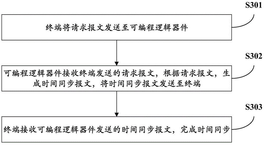
[0134] Such as image 3 The flow chart of the time synchronization method provided by Embodiment 3 of the present invention, such as image 3 As shown, the time synchronization method includes:

[0135] S301: The terminal sends the request message to the programmable logic device;

[0136] S302: The programmable logic device receives the request message sent by the terminal, generates a time synchronization message according to the request message, and sends the time synchronization message to the terminal;

[0137] S303: The terminal receives the time synchronization message sent by the programmable logic device, and completes time synchronization.

[0138] Specifically, the terminal communicates and interacts with the CPU or the programmable logic device in real time, so as to complete corresponding functions.

[0139] When the terminal needs to perform link establishment communication, the terminal generates a link establishment request message and sends the link establi...


PUM


Abstract

The invention provides a time synchronization method, a programmable logic device, a single board and a network element. The method comprises the following steps: the programmable logic device receives a request message sent by a terminal; the programmable logic device generates a time synchronization message according to the request message; and the programmable logic device sends the time synchronization message to the terminal. By adopting the time synchronization method in the technical scheme provided by the invention, the problem that a time synchronization response must be completed by software interruption due to the special limitation of a CPU architecture to result in definicient packet sending ability is solved. The programmable logic device frames and processes the time synchronization message and directly receives and sends the message to comprehensively improve the message processing ability, and a high-frequency accurate timing manner of the programmable logic device ensures a more accurate packet sending interval and further optimizes the time synchronization performance, therefore bandwidth resources of the Ethernet are used to the utmost to determine the message transceiving ability.

Description

technical field [0001] The invention relates to the technical field of communication, in particular to a time synchronization method, a programmable logic device, a single board and a network element. Background technique [0002] With the continuous development of communication technology, the industry is also committed to the solution of time synchronization technology solutions, respectively developed NTP (NetworkTimeProtocol, network time synchronization protocol) and PTP (PrecisionTimingProtocol, precise time synchronization protocol, namely IEEE1588) two protocols, Used for time synchronization between network devices. The PTP protocol uses GNSS (Global Navigation Satellite System, global satellite navigation system) or BITS (Building Integrated Timing System, building integrated timing system) clock as the clock source, and periodically synchronizes the clocks of all nodes in the network through synchronization signals, so that the Ethernet-based system can achieve P...

Claims


Application Information

Patent Timeline
Patent Type & Authority Applications(China)
IPC IPC(8): H04J3/06
CPCH04J3/0667H04J3/0697H04J3/0655H04L7/04
Inventor 汪立林万娟王仰锋傅小明
Owner ZTE CORP
Learn More