Flared laser oscillator waveguide

An expanded, waveguide technology for semiconductor diode laser applications

Inactive Publication Date: 2016-01-20
NLIGHT INC
View PDF7 Cites 2 Cited by
  • Summary
  • Abstract
  • Description
  • Claims
  • Application Information

AI Technical Summary

Problems solved by technology

However, the problem of scaling to higher powers while maintaining superior brightness still poses a challenge in the field of diode lasers, especially devices that are highly multimode on the slow axis, and thus requires improvements associated therewith

Method used


Image

  • Flared laser oscillator waveguide
  • Flared laser oscillator waveguide
  • Flared laser oscillator waveguide

Examples


Embodiment Construction

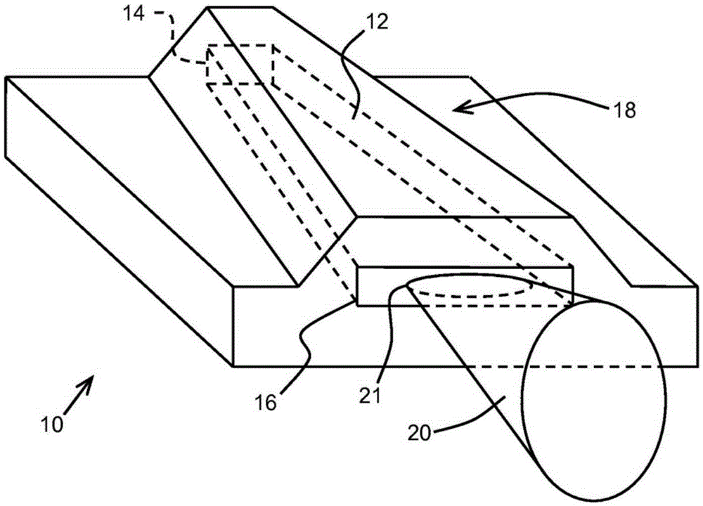
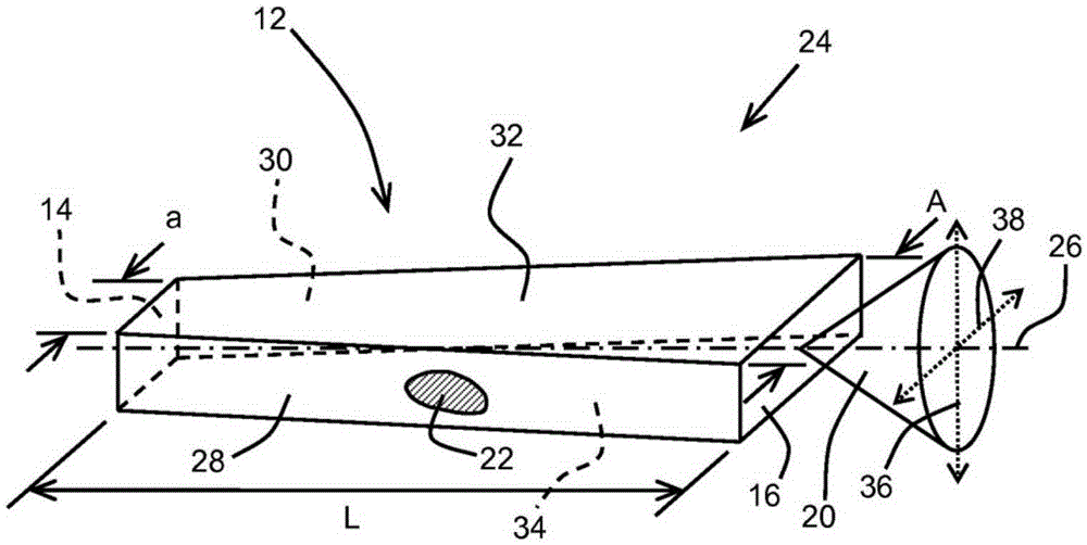
[0029] Reference figure 1 , Shows a first embodiment of a wide area expansion type laser oscillator waveguide (FLOW) device (generally designated as 10) according to an aspect of the present invention. The device 10 includes a current injection region 12 for electrical pumping, the region 12 having a trapezoidal shape extending between a highly reflective rear face 14 and a partially reflective front face 16. The device 10 may have a refractive index guide area such as figure 1 A ridge or flat top structure as shown 18, or figure 1 The shape 18 shown may be gain guided. The device 10 is configured to emit a laser beam 20 from its front face 16. When the light beam 20 is emitted from the front end surface 16 of the device 10, a beam spot 21 is formed on the front end surface 16 thereof. The ridge structure (especially its active part) may be partially made of a variety of different conventional semiconductor materials that are usually grown in layers by conventional semiconduct...


PUM


Abstract

A broad area semiconductor diode laser device includes a multimode high reflector facet, a partial reflector facet spaced from said multimode high reflector facet, and a flared current injection region extending and widening between the multimode high reflector facet and the partial reflector facet, wherein the ratio of a partial reflector facet width to a high reflector facet width is n:l, where n>l. The broad area semiconductor laser device is a flared laser oscillator waveguide delivering improved beam brightness and beam parameter product over conventional straight waveguide configurations.

Description

[0001] Cross references to related applications [0002] This application claims the rights and interests of the U.S. Provisional Patent Application US61 / 810,261 filed on April 9, 2013, and the entire content of the application is incorporated herein by reference for all purposes. [0003] Background of the invention [0004] 1. The technical field of the invention [0005] Generally speaking, the technical field of the present invention is semiconductor diode lasers. More specifically, the present invention relates to an expanded laser oscillator waveguide. 2. Background technology [0006] Multimode laser diodes (also known as broad-area lasers (BAL)) have the following properties: when they are driven with higher currents in order to generate higher power, their slow axis beam parameter product (BPP) and its slow axis The brightness (power÷BPP) gradually degrades. The brightness in the BAL can be improved by reducing the width of the emitter. However, the current at which the max...

Claims


Application Information

Patent Timeline
Patent Type & Authority Applications(China)
IPC IPC(8): H01S5/30H01S5/026
CPCH01S5/0287H01S5/1014H01S5/1203H01S5/1237H01S5/2018H01S5/2036H01S5/22H01S2301/16H01S2301/18H01S5/0651H01S5/1003
Inventor M·坎斯卡
Owner NLIGHT INC
Why Eureka
Try Eureka